This thread has been locked.
If you have a related question, please click the "Ask a related question" button in the top right corner. The newly created question will be automatically linked to this question.
Tool/software:
Hi TI Experts,
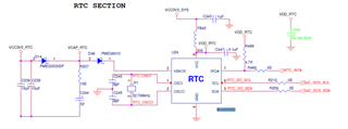
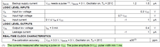
I am using BQ32002D RTC IC but it is taking 74.4 uA current from the backup supply which is way above the mentioned current in the Datasheet..
Below is my schematic for the same. Please let me know if there is any issue with the schematic.
Hi Mitul,
After switching from Vcc to Vback, back up current consumption is 1.5µA. However, if you simply provide a Vback to the device, the current will be much higher. We can resolve this behavior by toggling the Vcc pin. That is, provide a supply voltage to the Vcc pin for at least 1ms.
As for the schematic, if your crystal's loading capacitance meets datasheet requirement, the external loading capacitors are not needed.
Hi Noel,
Thanks for the reply but I do not get your point. What do you mean by toggling the VCC pin? Please explain.
It seems like that the RTC IC is not going in the Backup mode even though the power is shut off to the VCC pin. Do we need to do any software configuration for that or it goes by itself only?
Note: We have already removed the Load Caps from the Crystal.
Hi Mitul,
Noel has been OoO, he will return next week.
We will update you then.
Regards,
Vicente
Hi Mitul,
If you only apply Vback to the RTC without Vcc, the current consumption is going to be higher than specification.
At this time, you need to provide a pulse to the Vcc pin. The pulse duration has to be at least 1ms. When you apply the pulse to the Vcc pin, the RTC will switch to normal operation mode using the Vcc pin power supply. After the pulse, there is no Vcc, the RTC will automatically switch to use Vback. At this time, you will see the same current consumption as specified in the datasheet.
Hi Noel,
VCC [3.3V] is applied continuously when we are applying Vback to the RTC after power loss condition in our case.
But we are not giving any pulse to the VCC and we just directly applied 3.3V from the system 3.3V supply. So VCC [3.3V] is always available when the board is ON and when board is oFF then VBACK=3.0V is applied using superCap [3V & 5F]. Now in this circuit we have observed below point,
1. When Board is ON and VCC [3.3V] is applied, In this case Vback power consumption is 0mA but When board powered OFF and VCC is not applied [VCC=0V] then VBACK power consumption is Low 1.9uA - 2.1uA for initial few seconds around 50S and after this few seconds VBACK current consumption is increased by 30uA. So can you please explain why this current increased and how to keep resolve this.
And let us know that 1 ms pulse at VCC pin is mandatory ? What if we just normally applied this VCC [3.3V] continuously when board is powered ON?
Hi Mitul,
In your use case, you are switching over from Vcc to Vback, as such, you can ignore the 1ms pulse requirement.
I don't know why Iback changes after 50s. Could you measure the waveform at Vcc pin to see what happen after Vcc is power off?
Hii Noel,
Check the waveform of VCC while the VCC is powered off. [Note: 50s is not fixed here sometime Iback change after 20s, 30s means it is random but one thing we observed is that it is depend on Vback voltage]
Hi Mitul,
Do you know why Vcc goes up again? Is it due to Vback or system?
Datasheet requests a 1µF decoupling at Vcc pin, I don't know the reason for that but could you try if this can resolve your problem?