


Part Number: CDCE6214
Tool/software:
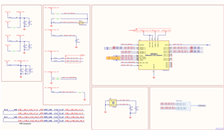

We are trying to bring up the CDCE6214RGE for a clock out of 100MHz 1V8 LVDS out at OUT2 and 27 MHz or 135 MHz out at OUT1.
We are using 25MHz crystal input for CDCE6214.
We are trying to configure the CDCE6214 by using I2C bus in our board.
Above is the configurations we have used.
We were trying with the Register Commit Flow method to program the EEPROM in Page 1.
We were unable to get the desired output.
Below is the hex values for the registers.
R85	0x00550000
R84	0x00540000
R83	0x00530000
R82	0x00520000
R81	0x00510004
R80	0x00500000
R79	0x004F0208
R78	0x004E0000
R77	0x004D0000
R76	0x004C0008
R75	0x004B0008
R74	0x004AA181
R73	0x00493000
R72	0x00480006
R71	0x00470000
R70	0x00460008
R69	0x0045A181
R68	0x00443000
R67	0x00430006
R66	0x00420006
R65	0x00410808
R64	0x0040A181
R63	0x003F1000
R62	0x003E4002
R61	0x003D0000
R60	0x003C6008
R59	0x003B8008
R58	0x003A502C
R57	0x00391000
R56	0x00380005
R55	0x0037001E
R54	0x00363400
R53	0x00350069
R52	0x00345000
R51	0x003340C0
R50	0x003207C0
R49	0x00310013
R48	0x003023C7
R47	0x002F0390
R46	0x002E0000
R45	0x002D4F80
R44	0x002C0318
R43	0x002B0051
R42	0x002A0002
R41	0x00290000
R40	0x00280000
R39	0x00270000
R38	0x00260000
R37	0x00250000
R36	0x00240000
R35	0x00230000
R34	0x00220000
R33	0x0021000A
R32	0x00200000
R31	0x001F0004
R30	0x001E0020
R29	0x001D0000
R28	0x001C0000
R27	0x001B0004
R26	0x001A0000
R25	0x00190401
R24	0x00180024
R23	0x00170000
R22	0x00160000
R21	0x00150000
R20	0x00140000
R19	0x00130000
R18	0x00120000
R17	0x001126C4
R16	0x0010921F
R15	0x000F5037
R14	0x000E0000
R13	0x000D0000
R12	0x000C0000
R11	0x000B0000
R10	0x000A0000
R9	0x00090000
R8	0x00080000
R7	0x00070C0D
R6	0x00060000
R5	0x00050008
R4	0x000400C0
R3	0x00031C00
R2	0x00020002
R1	0x00012310
R0	0x00001010
