This thread has been locked.

If you have a related question, please click the "Ask a related question" button in the top right corner. The newly created question will be automatically linked to this question.

LMK05318BEVM: 1PPS on LMK05318BEVM

Part Number: LMK05318BEVM
Other Parts Discussed in Thread: LMK05318B

Tool/software:

Hello,

I have a 1Hz signal (this is the GPS' synchronization PPS) that arrives in the LMK05318BEVM.

I would like to have this same signal coming out of the LMK05318BEVM (synchronized with the input one) when everything is fine and if I stop the input signal (for a long time, like few hours), I would like the output signal to continue as if the input signal had never stopped.

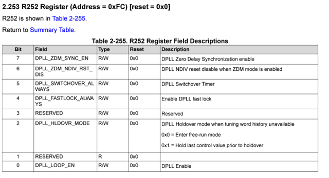
I did something on TICS Pro but the input signal and the output signal are not synchronized and when I want to activate ZDM in the "RAW registers", it stops the output signal.

Does anyone have a solution please?

Thanks, have a nice day. Slight smile


reglage_ticspro.tcsreglage_ticspro2.tcs

  • Hi Coline,

    LMK05318B ZDM is not a true zero delay. Rather, it is a pseudo ZDM because the device does synchronous reset to allow phase alignment on OUT7.

    Please check if 1PPS input signal has been validated: PRIREF_VALSTAT = 1 and DPLL lock: LOPL_DPLL = 0, LOFL_DPLL = 0?

    After enabling "ZDM", could you try a soft-reset to the device? Do you see output signal?

    -Riley

  • Hi Riley,

    Thank you for the answer. 

    I've got, as you the said :

    PRIREF_VALSTAT = 1 (The R411 register is : 0x019B0C)

    LOPL_DPLL = 0 ; LOFL_DPLL = 0  (The R14 register is : 0x000E00)

    And also : 

    DPLL_ZDM_SYNC_EN = 1 (The R252 register is : 0x00FCED)

    After soft-reseting the chip, I've got an output signal but it's still not synchronized with the input. Just like when there was no ZDM.

    My input signal is this one :

    On the oscilloscope, the input one is the yellow and the one from the LMK05318B EVM is the blue. As you can see, they aren't synchronized and the output one is not even the same exact frequency.


    For the registers, I use this document : www.ti.com/lit/ug/snau254a/snau254a.pdf?ts=1728438022259

  • Hi Coline,

    It is good that your setup is able to lock to 1PPS input since LOPL = 0 and LOFL = 0.

    It seems like you're looking for edge alignment between the 1PPS input & output.

    Could you try enable divider synchronization on APLL1 and OUT7:

    PLL1_P1_SYNC_EN = 1

    CH7_SYNC_EN = 1

    DPLL_ZDM_SYNC_EN = 1

    Then do a soft-reset

    You could adjust the phase offset through DPLL_REF_SYNC_PH_OFFSET


    -Riley