BQ4802Y: BQ4802Y: RTC not working in POWER OFF, Crystal not coming

Part Number: BQ4802Y
Other Parts Discussed in Thread: BQ32000, BQ32002

Tool/software:

Hi Team,

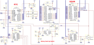
I am using BQ4802Y in my project. During testing i notice that when my device is ON RTC will work perfectly. but when i power off the device RTC will not work and when i again turn power ON RTC will start will the last reading it stops (as per save data in SRAM). 

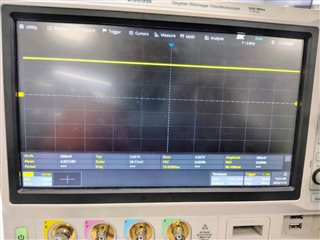
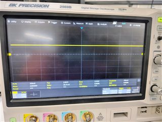
When i mesure crystal clock (Between Pin 3 and GND) during power ON state, i saw perfect 32.768 KHz frequency. but when i power off the device its a flat line (Like crystal is not generating clock). I don't know why RTC is not working in the power OFF state.

Please see atteched RTC section.


  • Hi Kaushik,

    What is the STOP bit set to?

    If STOP = 0, then the clock will stop when in battery backup mode.

    Regards,

    Max Verboncoeur

  • STOP bit is set 1

  • To debug this issue try multiple load capacitor with crystal.

    I tried original value from design is 20pF, then 10pF and even 6 pF capacitor at location C153, and C154. In all the test scenario clock does not able to generate.

    When i probe pin 3 when 6 pF capacitor is mounted, i see flat 1.53V on this line. While i increase capacitor from 6 pF to 20 pF the voltage on pin 3 is reducing but its always a constant voltage.

  • Hi Kaushik,

    See this previous E2E: BQ4802Y: BQ4802Y don't keep clocking in VBC mode - Clock & timing forum - Clock & timing - TI E2E support forums

    You may try removing the capacitors on the oscillator.

    Regards,

    Max Verboncoeur

  • Hi Max,

    I checked this test case but i don't think that RTC is corking in this case.
    Please find my test case and results.
    1. With original design (Load capacitance value is 20pF) 
         - When RTC is powered with 5V, Crystal is generating clock and RTC works fine.
         - When RTC is powered with battery, Crystal is not generating clock and RTC not working.

    2. With load capacitance of 6pF
         - When RTC is powered with 5V, Crystal is generating clock and RTC works fine.
         - When RTC is powered with battery, Crystal is generating 170 mV pk-pk clock with 700mV offset value and RTC not working (Time value not increment             when again power up RTC with 5V).

    3. Without load capacitance
         - When RTC is powered with 5V, Crystal is generating clock and RTC works fine.
         - When RTC is powered with battery, Crystal is generating 280 mV pk-pk clock with 730mV offset value and RTC not working (Time value not increment             when again power up RTC with 5V).

    4. I check power down time for 5V as well.
         - When main supply is turn OFF, voltage on 5V supply take around 2 sec time to reach 3V (Battery supply). As per datasheet, minimum requirement is 300          us. So, i don't think it should be create any problem.

    Please find atteched waveforms for reference.
    Crystal clock waveform.zip

  • Hi Kaushik,

    Looking at your crystal's specs, it has a 12.5pF load capacitance and 70kOhm resistance, which does not meet the 6pF and <45kOhm requirements for the device.

    Could you try swapping for a crystal that meets the device requirements and see if that resolves the issue?

    Regards,

    Max Verboncoeur

  • Hi Max,

    I have following 2 crystals available with me.
    1. 830107088501 (32.768 kHz ±20ppm Crystal 6pF 90 kOhms)
    2. ABS07-120-32.768KHZ-T (32.768 kHz ±20ppm Crystal 6pF 55 kOhms)

    The observation are slimier for both parts. RTC does not work in battery backup mode and working in 5V supply.
    Crystal clock waveforms also similar to previous.

    Please find atteched waveforms for reference.

    Crystal Part 830107088501.zipCrystal Part ABS07-120-32.768KHZ-T.zip

  • Hi Kaushik,

    Did you test without the probe connected to the crystal to see if it functions in that state? It could be that the probe capacitance is too high and interfering with the clocking.

    Also, did you check CEOUT to see if it is driving to V_OHB?

    Regards,

    Max Verboncoeur

  • Yes I check the RTC without probe. In 5V supply RTC will increment time and I can see it on terminal. When I turn off 5V supply, and RTC works on battery power we doesn't have provision to see time in terminal. When I again turn 5V on RTC again start working and start incrementing time but with last time before 5V off (it should be 5v on time + time in battery power).

    In my design, I doesn't connect CEOUT with any device. It's floating. One more thing I could not found any voltage level for V_OHB. Can you provide me it's voltage level?

  • Hi Kaushik,

    There doesn't seem to be a value for V_OHB. It may be based on the battery voltage.

    If you probe the pin while the device is running on the battery, what do you read there?

    Regards,

    Max Verboncoeur

  • Hi Max,

    When device is powered with 5V, CEOUT pints stay at 5V.
    When device is powered with 3V, CEOUT pin stay at 2.7V.


  • Hi Max,

    I try to look into power sequence of RTC for 5V and battery and power swtiching from 5V to battery. 
    I had atteched waveforms in below zip file. please have look into it. 
    Where,
    Channel C1: Yellow    : Probe at VCC and VCC is shorted with CEIN as per schematic
    Channel C2: Pink       : Probe at CS pin
    Channel C3: Sky Blue: Probe at RST line

    Power Sequence.zip

  • Hi Kaushik,

    I think the device is successfully in battery backup mode since the crystal is being clocked, and VOHB=2.7V sounds about right.

    The only thing I can think of at this point is that the crystal you are using is not fully meeting the spec required by the device.

    Regards,

    Max Verboncoeur

  • Hi Max,

    I don't think crystal is creating issues. Can you suggest some part number so I can check with it.

    Also, is the any other resister setting or hardware configuration or timing requirement?

    Also one more observation, As per my schematic design When RTC power by VCC, CS pin voltage is around VCC, but when RTC power by BC (3V), CS pin voltage is around 2.6V. As per datasheet VIH is minimum 2.4V. 

    Please suggest your thoughts on this.

  • Hi Kaushik,

    Something like the CFS-20632768DZBB with an ESR <45kOhms is worth a try.

    Also one more observation, As per my schematic design When RTC power by VCC, CS pin voltage is around VCC, but when RTC power by BC (3V), CS pin voltage is around 2.6V. As per datasheet VIH is minimum 2.4V. 

    This should be fine since it meets the minimum spec.

    For future developments, I suggest looking into the BQ32000 or BQ32002. The BQ4802Y is almost 25 years old, so design support is very limited.

    Regards,

    Max Verboncoeur

  • Hi Max,

    i changed obsolete part with this RTC chip. since our existing design MCU does not have serial interface like I2C. so i can not use your suggested chip set.

    I observe something today,
    When RTC is powered with 5V, VOUT is 4.95V
    When RTC is powered with 3V, VOUT is 2.5V

    I do not know why 0.5V drop happening in battery back up mode.

  • Hi Kaushik,

    That's an interesting observation. The output should only drop ~0.3V at most from the supply voltage. Did you check that the voltage right at the BC pin is 3V as expected? Also, is the BC pin voltage applied from startup?

    Regards,

    Max Verboncoeur

  • Hi Max,

    Yes i checked the BC pin voltage and it is 3V. Currently i am providing 3V battery voltage with external RPS power supply in stand of coin cell. BC pin voltage turn ON before voltage on VCC pin appears. ether way i doute that power sequence for BC and VCC has impact on VOUT voltage.

  • Hi Kaushik,

    So that we can totally rule out the crystal as a potential factor, could you try removing the crystal and connecting a function generator between X1 (+) and X2 (-) set to 32.768kHz and ~3V amplitude?

    Regards,

    Max Verboncoeur

  • Hi Max,

    I will check it and update the results.
    Meanwhile can you help me resister setting. When i measure current consumption on battery in battery backup mode, it will consume around 14 mA current. As per datasheet it should be of around micro Amps. Can you provide resister settings to put device into Low Power Mode. 

  • Hi Kaushik,

    That is rather high. Are you measuring that current across R77? Could U19 be responsible for some of that current? Is anything else connected to the battery? Is there any load on V_OUT or CE_OUT?

    You might also try swapping the unit out for a fresh one in case something was damaged.

    Regards,

    Max Verboncoeur

  • Hi Max,
    Currently R77 value changed to 0E. Yes i am measuring current in between R77 and BT1. U19 is simple battery back up switch with provide output of eighter 5V or 3V (Battery) which ever is higher.
    In my earlier similar design, BT is connected with U19, SRAM, OR Gate, and Old RTC in that current at BT is in micro Amp, but in new design only RTC part is changed and i observe current in 7-8 mA.

    Sorry about 14 mA, I check it again with preside instrument and it come around 7-8 mA.

    Request you to provide your response soon, since i need to close this issue ASAP.

  • Hi Kaushik,

    Is there any load on V_OUT or on CE_OUT? The spec in the datasheet states that the current was characterized with no load on these pins.

    Regards,

    Max Verboncoeur

  • Hi Max,

    No there are no load at both pins.

  • Hi Kaushik,

    Have you tried swapping the IC for a fresh one to see if this is an issue with the IC itself?

    Regards,

    Max Verboncoeur

  • Hi Max,

    We are running some  hardware test to debug this issue.

    We will also check the issue by replacing RTC and some other ic.

    I will update you as soon as I conclude the test.

  • Hello Max,

    During high current issue debugging we identify some things and conclude that RTC is consuming 0.4 uA current.
    Also we have observed some other parameters as below.
    - In battery backup mode U21 pin 21 (CS) remain high as per our schematic design.

    • In that condition when we measure voltage at pin 28 (VCC) we observe 1.3V (It should be 0V)
    • When we disconnect CS pin at RTC, we observe 0V at pin 28 (VCC)


    • Impedance between U21 Pin 21 and U21 Pin 28 (VCC) is 8.3 M Ohm
    • When U21 pin 21 (CS Pin) is disconnected and Voltage at U21 pin 28 (VCC) is 0 V.
    • When U21 pin 21 (CS Pin) is connected to external 3V supply, Voltage at U21 pin 28 (VCC) is 1.98V and current consumption at pin 21 is 27 mA.

      Please you share your thoughts on leakage current to VCC pin.
  • Hi Kaushik,

    That seems abnormal. It could be that when VCC is low, the CS pin being more than 0.3V above VCC is causing an internal diode to go into breakdown. The abs max ratings seem to agree with this:

    I wonder if the testing results change on a fresh IC if CS is brought low before VCC is removed.

    Regards,

    Max Verboncoeur

  • Hi Max,

    I debug this issue further and observe that it not just CS pin but other input pins OE, WE, RST is also responsible for this issue.
    When i remove RTC is from board and standalone apply 3V to above input pin one at a time with GND, i observe same behavior as with CS pin.

    Does this chip works this way or we had issue with IC lot? I wonder what's the reason.

  • Hi Kaushik,

    I think this is just how the chip is. I believe that the assumption in the design was that the input pins aside from BC would be driven by the same source as VCC, and would fall to 0V along with it.

    Is there any update on using the function generator in place of the crystal?

    Regards,

    Max Verboncoeur

  • Hi Max,

    We had ordered few RTC chips to check Current leakage issue. Let's see does this is a way chip design or not.

    Yes, I tried with function generator in stand of crystal but in that case RTC does not start even in 5V supply. May be RTC ment to use with crystal only.

  • Hi Kaushik,

    The part should not distinguish between a crystal and a function generator. Perhaps the signal isn't quite right.

    Let's see how the new parts perform.

    Regards,

    Max Verboncoeur

  • Hi Max,
    We receive the new crystal part (ECS-.327-6-34RR-TR) and with this part 3 boards are completely working.
    We are trying to test this with multiple boards and try to check time accuracy as well.

    Also i have one more que:
    If i want to use CEIN and CEOUT pins of RTC, what is time delay between this 2 pin for low signal level (Since by default CEIN is high so will CEOUT).

  • Hi Kaushik,

    I am glad to hear that it is working now!

    If i want to use CEIN and CEOUT pins of RTC, what is time delay between this 2 pin for low signal level (Since by default CEIN is high so will CEOUT)

    That would be the t_CED spec:

    Regards,

    Max Verboncoeur

  • Hi Max,

    We have tested multiple board and RTC is working but we observe time drift in that case.
    When C153 and C154 are mounted with 6pF capacitor we observe 4 sec time lagging in 12 Hours. We have kept multiple device in testing with different load capacitor.

    Meanwhile, Can you suggest what are you recommend value for c153 and c154 as per you?

  • Hi Kaushik,

    C153 and C154 are not recommended. These are most likely increasing the load capacitance of the crystal past the 6pF spec. The crystal will have its own load capacitance which you can find on its datasheet, and it should not need extra capacitors.

    Regards,

    Max Verboncoeur

  • Hi Max, 

    I tested board with removing C153 and C154, but in that case we observe 3 sec time advance than actual one.

    I have put some board with different load capacitance value in long run testing to check their effect on time.
    Please suggest your suggestion and feedback on this.

    Also this is the crystal part we are using now, "ECS-.327-6-34RR-TR"

  • Hi Kaushik,

    This definitely sounds like the capacitance is slightly off. It might be necessary to tweak the load capacitance slightly to find the optimal value.

    Regards,

    Max Verboncoeur