Because of the holidays, TI E2E™ design support forum responses will be delayed from Dec. 25 through Jan. 2. Thank you for your patience.

This thread has been locked.

If you have a related question, please click the "Ask a related question" button in the top right corner. The newly created question will be automatically linked to this question.

LMK00308: LVDS outputs with AC coupling to receiver with internal 100 ohm termination

Part Number: LMK00308
Other Parts Discussed in Thread: , LMK00306EVM, LMK00306

Hello,

I have a question about LMK00308.

[Background #1]

The LVDS interface circuit with AC coupling to receiver with internal 100 ohm termination is listed in the datasheet as follows.

<D/S(snas576d) P.26 10.3.2 Termination for AC Coupled Differential Operation> 

When driving a differential receiver with internal 100 Ω differential termination, a source termination resistor
should be placed before the AC coupling capacitors for proper DC biasing of the driver as shown in Figure 34.

[Background #2]

The following application is shown in scaa059c.

[Background #3]

By default, CLKoutB# is configured for LVDS output in LMK00308EVM.

This circuit is same as Figure 12 in scaa059c.

[Q]

Is source termination resigter really necessary when driving a differential receiver with internal 100 ohm differential termination?

Is CLKoutB# LVDS circuit in LMK00308EVM wrong ?

Best Regards,

Hiroshi Katsunaga


  • Hi all,

    Do you have any update on this post ?

    I received pressing from them.

    They need a right information ASAP.

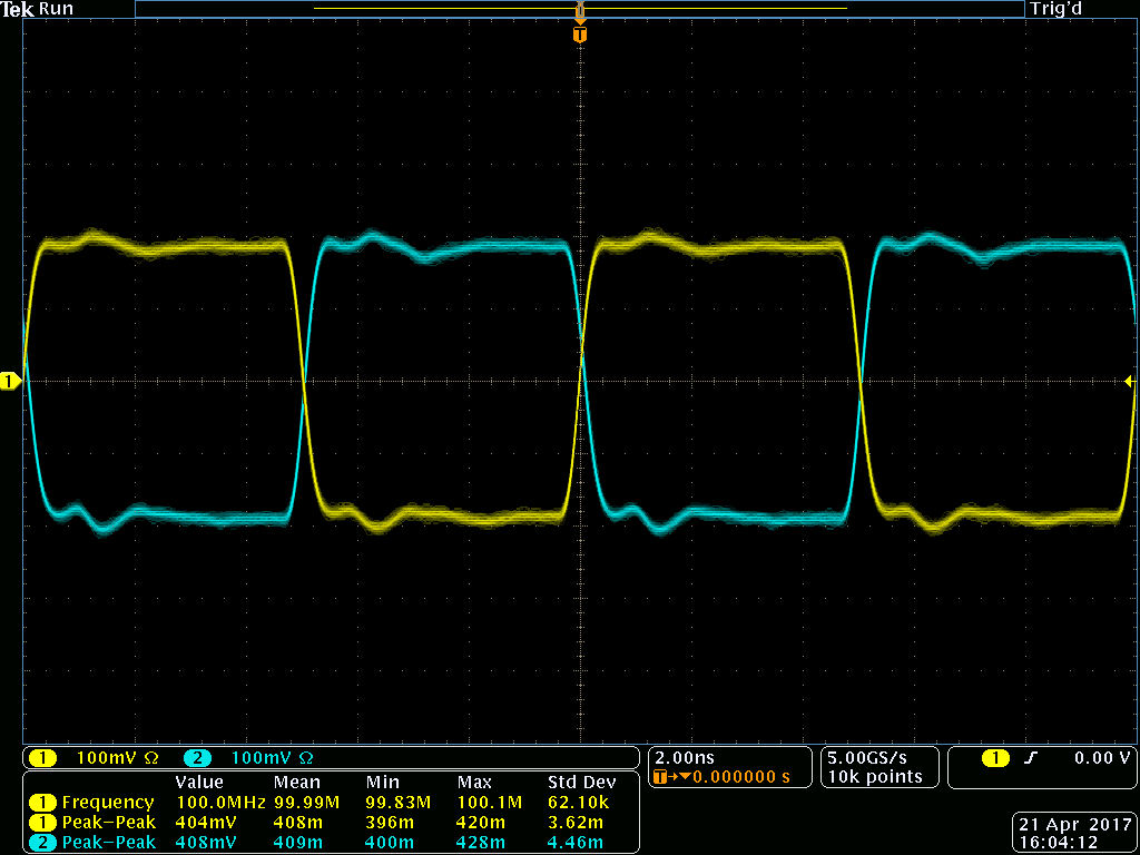
    I measured LVDS output with default configuration (termination after AC coupling)  in LMK00306EVM.

    The result as follows.

    It looks no problem.

    The common mode voltage of the LMK00306 output looks 1.2V.

    I think it is the proper DC bias point for the driver (LMK0030x).

    I think the description of the datasheet is wrong.

    Please reply it. 

    Best Regards,

    Hiroshi Katsunaga

  • Hello Katsunaga-san,

    I apologize for the delay in our response.

    My understanding is that with the LMK00306 LVDS driver, to ensure a robust start-up when AC coupled, it is necessary to place 100 ohms with a DC connection to the output. This could be as illustrated in the figure above (figure 34 from datasheet) for devices with integrated terminations. Or it could be as figure 33 in datasheet which shows, LMK00306 LVDS driver --> Transmission Line --> 100 ohms ---> AC coupled --> Target device (with self bias) if the termination is not integrated. This would allow the driver to have 100 ohm DC load, without having two 100 ohm in the setup.

    My understanding is the datasheet is correct. I will confirm with others and see about making an update to the LMK0030x eval board instructions.

    Please refer to this E2E thread for more details: e2e.ti.com/.../526577

    73,
    Timothy
  • Hi Timothy,

    Thank you for your response.
    I understood your comments.
    However I think the figure 34 is too much idea for listing it in the D/S because this is not the issue in this device family but the issue in the LVDS interface.
    I think that this description loses an opportunity because it may cause misunderstanding.

    Thank you for your cooperation.

    Best Regards,
    Hiroshi Katsunaga