


Other Parts Discussed in Thread: CDCLVP1204, CDCLVC1103
Hi team,
The customer would like to use CDCLVP1204 + LMX2582. The input frequency is 100MHZ. He needs to output 100MHZ, 2GHZ and 4GHZ.
The output frequency 100MHZ is used as the input frequency of FPGA. He would like to use LMX2582 to output 2GHZ and 4GHZ.
Please check the attach fig 1 for the customer's requirements.
For the customer's requirements, I use Webench to do a simulation, fig2. From the simulation result, I will recommend CDCLVC1103.
And the the simulation result that it will be needed two LMX2582 devices.
Q1: LMX2582 has two output channels. They are A channel and B channel.
Are the customer's requirements needed two LMX2582 devices, like my simulation result?
Q2: The customer needs to calculate the loop filter. Can the customer refer to the simulation result fig 3? Do you have any better suggestions?
Q3: The customer would like to get how to configure the registers for his requirements. Do you have any suggestions? Can I recommend
the TIS Pro software to configure the registers if the customer uses his board?
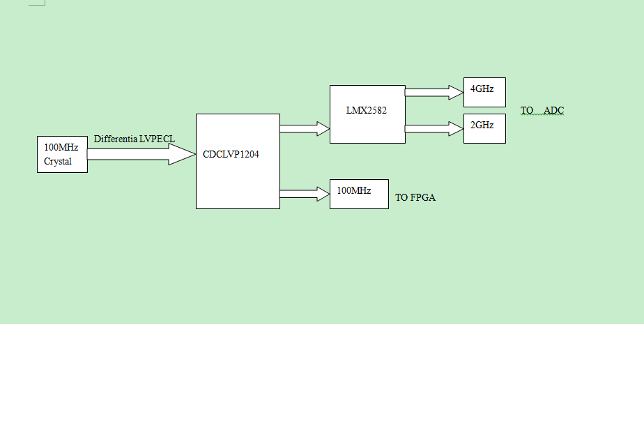
Fig 1
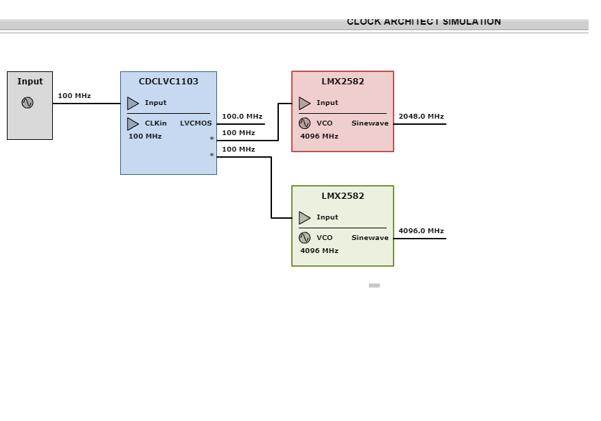
Fig 2
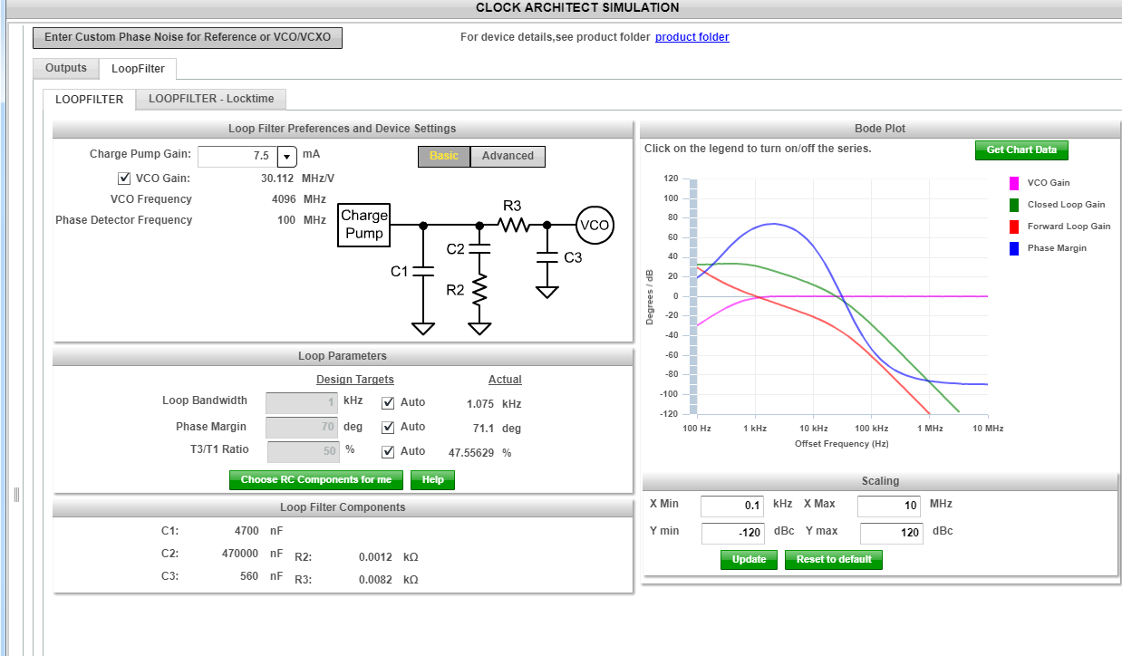
Fig 3
Best Wishes,
Mickey Zhang
Asia Customer Support Center
Texas Instruments