A related question is a question created from another question. When the related question is created, it will be automatically linked to the original question.
If you have a related question, please click the "Ask a related question" button in the top right corner. The newly created question will be automatically linked to this question.
TLC556: I would like to use 1/2 of 556 as one shot to turn other 1/2 astable pulse generator on/off. Regards, Erik
Connect output pin of timer A to the reset pin of timer B. Timer B will run only pulses when Timer A is high (one shot running). Timer B will normally be static output low. First A-stable high pulse will be longer because timing capacitor starts at 0V and all of the remaining pulses will start at 1/3 VDD. Adding a PNP transistor and 2 resistors can precharge the cap to 1/3 VDD. The last pulse could be cut short if the mono stable (Timer A) goes low in the middle of the stable outputting a high pulse level.
Use TLC555 A-stable calculator tool, , to choose components for A-stable timer.
R6, T1, and R4 precharge the cap C2. Set R4 = 2 * R2 and R6 is not critical, 5 * R4 is fine.
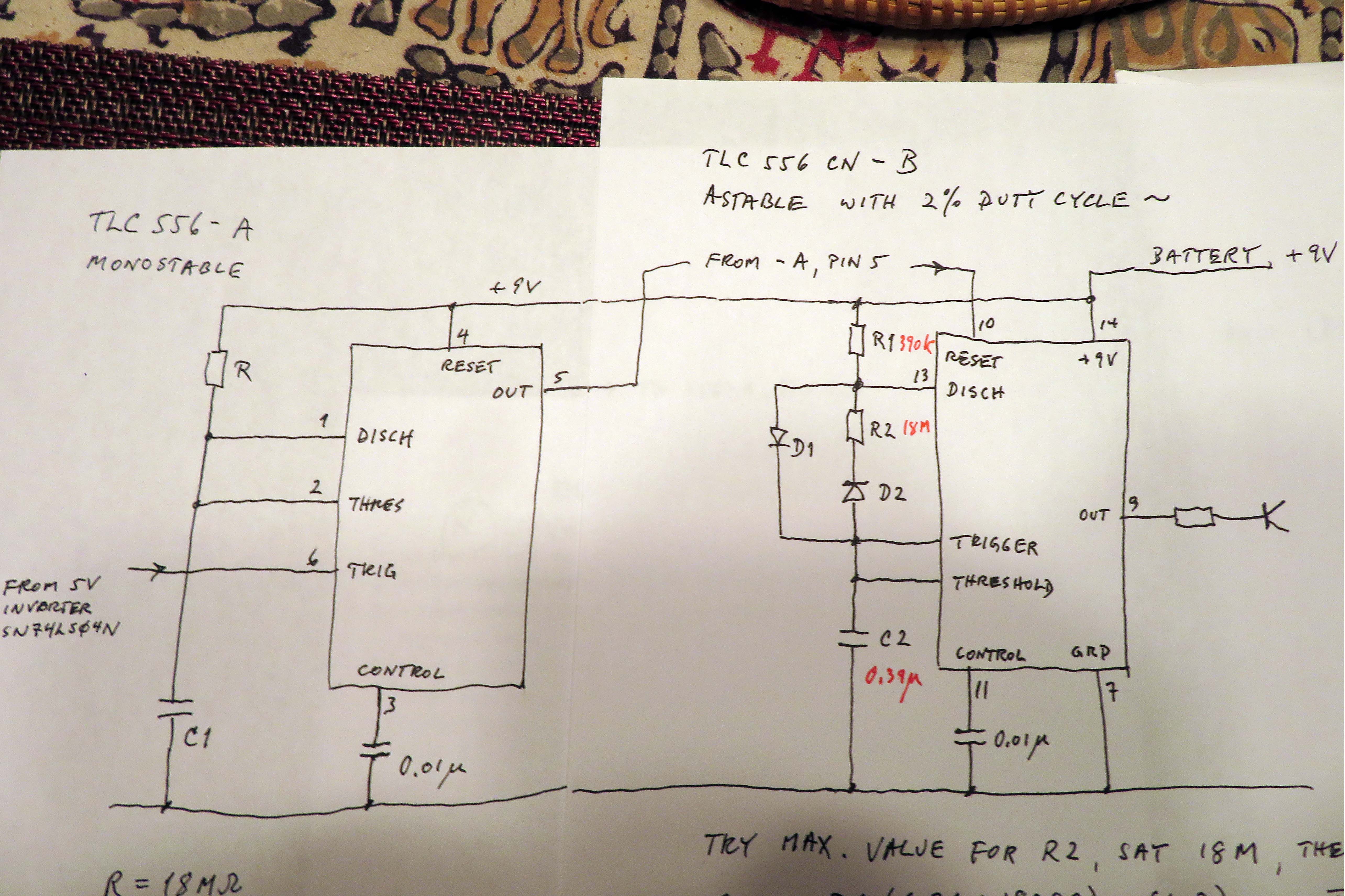
I have selected some component values ( that recommended calculator did not get through my old computer...). I ended up with the enclosed sketch. Could anyone check it out? I have not done any detailed design for quite a few years..
1. It does not matter if first pulse is up to 2x as long as others
2. It does not matter if last pulse is cut off
3. would like high resistance values to keep Cs down
4. The monostable output shall stay high for about 30 seconds
5. The astable must reliably start and run for that time only, producing about 6 pulses, each approx. 100 ms long, once every 5 seconds
A. I picked following values:
R 18 M
C1 1.5 microF
R1 390 k
R2 18 M
C2 0.39 microF
D1 & D2 are 1N4148
Chip is TI TLC 556 CN, 14 DIP for prototype
What is recommended decoupling between pins 14 & 7 ?
The TLC555 datasheet recommends using both bypass capacitors
• C3—0.1-μF bypass ceramic capacitor
• C4—1-μF electrolytic bypass capacitor
The SN74LS04 VOH output might not be high enough for trigger input. Use SN74HC04N instead.
With 18M ohms resistors and 9V power the minimum timing current will be 9V/3/18M = 167nA . The total leakage current in the application must be less than that value. so I recommend keeping temperature below 70C