This thread has been locked.
If you have a related question, please click the "Ask a related question" button in the top right corner. The newly created question will be automatically linked to this question.
Hi ,
1. i was working with ADS114S06B and it is interfaced to Raspberry pi using spi interface. i was to unable to read any data from ADS114S06B , i was in confusion that whether the device is working or not. can you please suggest a way to test the device
2. i was gone through the below link ADS114S06: SPI Communication with ADS114S06 - Data converters forum - Data converters - TI E2E support forums
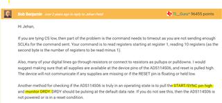
in this link they have mentioned that by pulling start/sync pin high and monitor DRDY, DRDY will give pulse with default data rate , whether it is possible with out any reference voltage.
Thanks and Regards
Pradeep Gamidi.
Hi Pradeep,
For the ADS114S06B to operate and communicate properly all supply voltages (AVDD/AVSS, DVDD and IOVDD) must be at a valid operating level. It is also important that the RESET pin on the device is pulled high. You do not need a valid reference to check if the ADC is converting. If you pull the START/SYNC pin high the DRDY output should pulse approximately every 50ms.
Best regards,
Bob B
Hi Bob,
Thanks for quick reply, i was able to see 20hz in oscilloscope i can see only one pulse on scope but i cannot see any pulse train.
is there any pre setting need to be done on master side to read data from ADS114S06B?
i was configured with following settings
1. sclk speed 5000000 hz
2. mode 1
3. i was making chip select low when ever i was transferring data
4. i was reading status register by sending 0x25 to ADS114S06B (this data i can see on DIN pin using scope) but the device is not responding.
Please suggest where i was missing to read data.
Regards,
Pradeep Gamidi.
Hi Pradeep,
I should have also mentioned that the CLK pin should be connected to DGND to make sure that the internal oscillator is running.
The SCLK speed may be too fast if this is a prototyping development system. I would slow the SCLK speed down maybe to 1MHz until communication is verified.
Also CS must be low for the entire communication transaction otherwise the communication is cancelled on the rising edge of CS. This means that if CS is toggling for each byte, the communication will not complete as desired. For example, the read register (RREG) operation is multi-byte made up of at least three bytes. The first byte includes the RREG command and the starting register to be read. The second byte contains the number of registers to read - 1 and the third byte is a NOP which would also clock out the register data. The STATUS register is register 1. The operation and commands transmitted are as follows:
Usually the best way to check your communication is to use an oscilloscope or logic analyzer. If you are still having issues can you send me your schematic and scope or logic analyzer shots of the communication on the SPI bus?
Best regards,
Bob B