This thread has been locked.

If you have a related question, please click the "Ask a related question" button in the top right corner. The newly created question will be automatically linked to this question.

DDC264EVM: resistors that series to input side of ddc & measuring offset value

Part Number: DDC264EVM
Other Parts Discussed in Thread: DDC264

Hi

I'm using DDC264EVM and I have some question. 

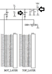
1. i connected just one sipd to the point that it was shown in picture below and also connected pin 1 to pin 2 of jumper 10 to read the data. as you can see in this picture, 25 resistors series to the input pins of ddc264. 

my question is that, the value which i read in the software is correct value or i have to multiply it by 25. because i assumed the amount of current that produce by sipd is divided into 25 parts (25 input of ddc).

2.we used ddc264 ic in our customized board. the amount of offset that we measure in our experiment is about 3100 which is different from the amount that you mentioned in link below (4095).

my question is that, is there any negative swing in our experiment which is affected our offset value or this is normal to read this amount of offset.

  • Hi Sajjad,

    1. Any current from the SiPD will be distributed to all the channels connected to the same source through the resistors. The purpose of the resistor is that a voltage source can be applied to the Vin to create a current to be integrated by the device. Therefore, you do not use those resistors when you connect your sensor.

    2. By design, the device has an offset (~0.4% FSR) included in the output to allow slightly negative input from clipping the input. Any additional input to the channel will affect this offset reading.

    Thanks

    -TC

  • Hi Again

    thank for your answers

    according to question 1: there is any way other than removing the resistor from board and short circuit pins when I am using current sensor(SiPD) ? I mean any solution without manipulation the board.

  • Hi Sajjad,

    The AIB board (Analog Input Board) is intended to be used to evaluate the device and not for connecting other sensors to it. You will need to create your own custom board or modify the AIB board for your application.

    Thanks

    -TC