This thread has been locked.

If you have a related question, please click the "Ask a related question" button in the top right corner. The newly created question will be automatically linked to this question.

ADC12DJ5200RFEVM: ADC12DJ5200RFEVM

Part Number: ADC12DJ5200RFEVM
Other Parts Discussed in Thread: ADC12DJ5200RF

Problem consultation and help seeking.rar

  • Hi Sun,

    What is the question on the ADC12DJ5200RF EVM?

    Regards,

    Rob

  • Hi Sun,

    Can you please have customer use the JMODE30 on the ADC and also JMODE30 on the dropdown ADC12DJ5200RF_JMODE30 ini file in HSDCpro from the dropdown. 

    Regards,

    Neeraj

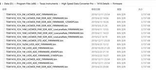
  • Thank you very much. Your suggestions are very helpful, but I still have some new questions. If I want dual-channel sampling, that is, each ADC with 5.2gs/s sampling rate works alone, should I choose JMODE31? Dose the ADC12DJ5200RF_JMODE30 ini file still work? If not, what should I do? Secondly, there are 71 JMODEs. What's the difference? Which JMODE do I usually choose for the ADC I use? If I select JMODE 40 and JMODE 41, would the ADC12DJ5200RF_JMODE30 ini file still work? How can I use these three ADC ini files “ADC12DJ5200RF_JMODE0_TI_IPADC12DJ5200RF_JMODE10_TI_IPADC12DJ5200RF_JMODE21_TI_IP”? There are so many firmwares in the "FireWare" folder. How should I use them and what is the difference between them?

  • Dear Neeraj,

    Thank you very much for your last reply. Your suggestions are very helpful to me. I tried JMODE31and ADC12DJ5200RF_JMODE30 INI file working at the same time. In this case, HSDC Pro software can also work, but it does not realize the independent work of two ADCs, just cross synthesize the collected data together. Only channel 1 / 1 appear in the software but no channel 2, and J4 (INA) and J7 (INB) need signals at the same time, and they must be the same signal.

     My question is, how can I operate to realize two ADCs working alone and sampling different input signals (INA and INB)?

    Bestwishes

  • Hi Sun,

    Please copy the attached INI file to following location on your pc. 

    C:\Program Files (x86)\Texas Instruments\High Speed Data Converter Pro\14J58 Details\ADC files

    ADC12DJ5200RF_JMODE31.ini

    Disconnect and then reconnect to the TSW14J58 board and selected the ADC12DJ5200RF_JMODE31 file from HSDCpro drop down. It should give you two channel output.

    Regards,

    Neeraj

  • Dear Neeraj,

    Thank you very much for the file you provided last time, which helped me a lot. I still hope to get your guidance on the following questions.

    I read the manual of the ADC12DJ5200RF and found the following description:

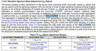
    I'm not sure whether my understanding is correct. Does it mean that the sampling point can be adjusted by controlling the delay, and the delay accuracy can reach 19fs? I would like to know how to realize sampling point (phase) delay control by operating on the ADC GUI software? Besides, how long can the maximum delay reach?

    In addition, the manual also mentions that the full-scale input voltage is 0.8V VPP (peak to peak), and the screenshot is as follows:

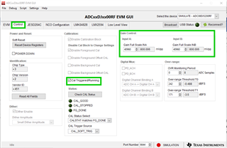
    But I tested in the JMODE30 mode at a sampling rate of 10.4GS/s. When I input the 260MHz RF signal of about 1.31V VPP, the sampling result is close to the full range. Are there several different voltage range options? What are they respectively? How can I operate to select different ranges?

    Thank you again for your hard work.

    Best Wishes!

  • Hi Ao,

    Here is the para from the datasheet which discuss the aperature delay and the min and max adjustment. 

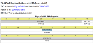
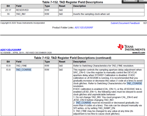
    The aperture delay adjust can be changed with following register. 

    2. The default fullscale range of the ADC is 800mV peak to peak but this range can be changed in the ADC gui. 

    Please remeber to perform calibration once the full scale range is changed. 

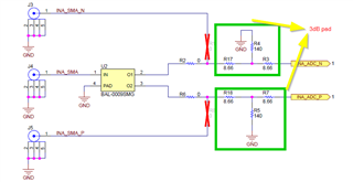
    Also there is a 3 dB attenuator at the input of the ADC path

    Regards,

    Neeraj