This thread has been locked.

If you have a related question, please click the "Ask a related question" button in the top right corner. The newly created question will be automatically linked to this question.

ADS4449: high-data bus bits unexpectedly toggling

Part Number: ADS4449

The attachment in the related thread has two charts, with digital functions enabled and disabled.  Both charts are identical.  Is that correct?

If only one or two channels are being used, and the unused channels are not terminated, will that cause high-bit toggles on all channels or just the unterminated channels?

Can this be mitigated by powering down the unterminated channels and/or setting the test pattern to all zeros (or custom pattern for mid-scale)?

e.g. if there is a large deployment in remote locations with unterminated channels, can the problem be mitigated by effectively "disabling" those unused channels in software somehow (to avoid the bit toggles on the used channels).

Thanks, Brendan.

  • Brendan,

    Yes, the chart has two identical plots. This was an error, but if I remember correctly, in both cases, the results were almost identical.

    The 4 channels are isolated so I do not think the unterminated channels will affect the terminated channels.

    I would suggest powering down the unused, unterminated channels.

    Not sure what you are asking in your last question. In all cases, if a channel is not use, I would power it down.

    Regards,

    Jim   

  • Thanks Jim.

    The last question was really just a restating of the first (from an existing deployment perspective).

    Since there is no issue with an unterminated channel (no input cable connected) affecting a terminated channel (input cable connected), then I doubt it will solve an issue we are seeing with some deployed devices, though powering down unused channels seems prudent.

    There is a possibility that the VCM at the analog inputs might be out of spec.

    We have 100nF cap to VCM, but it is in series with a 100ohm resistor.

    At 250MHz sampling rate and 1.5uA/MSPS this could cause a larger voltage drop across the resistor (maybe 37.5mV, which would be outside the +/-25mV recommended range).

    If VCM at analog input is out of the +/-25mV range, what would be the effect?  Could it cause higher order data bits to flip?

    Thanks, Brendan.

  • Brendan,

    Can you send your schematic? Is the 100nF cap between GND and the VCM pin? What is the purpose of the 100 Ohm series resistor?

    If the VCM goes outside the +/-25mV range, the upper bits may toggle but the VCM would have to be different on the INP and INM pins. Since the analog input is differential, if the VCM is the same on both pins, I do not think the the upper bits would toggle.  Any idea what the VCM is at on both analog input pins for each channel when you see this issue?

    Regards,

    Jim

  • Hi Jim,

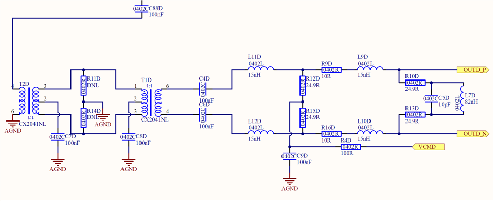
    Here is a snippet of the ADC input circuitry (for channel D).  Not shown is some other input filtering and a programmable analog attenuator feeding C88.

    The 100ohm resistor (R4) was suggested by an FPGA/analog engineer to reduce noise on VCM.  I am following up with him for some further advice.

    I could not measure VCM across the cap as it is not easily accessible and there is no test point.  I was able to measure VMC, OUT_P and OUT_N (DCV using a basic multimeter) if that helps any.

    • VCM = 1.158V
    • OUT_P = 1.071V
    • OUT_N = 1.071V

    Is the 1.5uA/MSPS a DC or AC value?

    If DC, then I don't see how the cap can get up to VCM due to the voltage drop across R4.  If it is AC or mostly 0A then it could be ok.

    Your thoughts please Slight smile

  • Brendan,

    I think 1.5uA/MSPS is AC but checking into it.  

    On our setup in the lab, when no input was applied, I was able to observe many upper bits toggling. This was due to the fact that with no input, the ADC output was at midscale +/- a few bits. With the output switching between 1FF0 - 200F, you will see all of the bits toggling. By any chance, is this what you are seeing? I only noticed this on one of the four channels as each channel had a slightly different offset. If the output was slightly higher or lower than midscale, only the LSB's would be toggling. 

    Regards,

    Jim 

  • Brendan,

    See attached document from our design team regarding your question about 1.5uA/MSPS.

    Regards,

    Jim

    Common mode.docx