This thread has been locked.

If you have a related question, please click the "Ask a related question" button in the top right corner. The newly created question will be automatically linked to this question.

ADS8168: ads8168, ref issue

Part Number: ADS8168

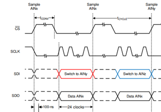
1ST channel of ADS8168 , have a constant reference voltage (2.04v), my signal is 0-  5 v but adc divide it to +v half cycle and - ve half cycle correspond to that voltage (2.04), how to chage it.  

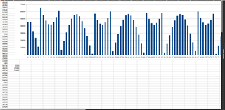
, this wave because of -ve half cycle (below 2.04v) signal is 2's complemented by adc,  i want this signal as proper sine wave 

  • Hello Sudheerthan,

    First, welcome to the TI E2E Community!

    Can you include a picture of the schematic so I can better understand how you have the ADC connected?

    1. If you want to measure a 0-5V input voltage, you must use a 5V reference, connected to the REFIO pin 3.  In this case, the AVDD supply will need to be operated between 5.3V and 5.5V to provide proper voltage headroom for the internal reference buffer.

    2. I suggest you configure the ADC for Single-ended configuration, which is the default setting after power-up.  In this case, the AIN-COM pin 8 should be connected to ground.  The output coding is always in straight-binary format, not 2's complement.  Using a 5V reference voltage, applying 5V to the input will result in an output code of 0xFFFFh, apply 2.5V will result in an output code of 0x8000h, and 0V input will result in an output code of 0x0000h.

    Regards,
    Keith Nicholas
    Precision ADC Applications

  • hi, keith nicholas, 

    my input voltage is between 0-5v not exactly 5v , and that connected to REFIO pin 3, properly , also AIN-COM pin 8 is connected to ground, but when i read ADC and plot it , it looks like above graph, , some where at mid (2.04v) it divided into + ve and - ve  half cycles i think, 

  • Hello Sudheerthan,

    Please capture a full 16b frame using either an oscilloscope or logic analyzer, similar to Figure 42 in the datasheet.  Based on my understanding of your setup, you have 5V connected to REFIO pin 3.  Please apply 2.5V to the input, either from an external voltage source or from the REFby2 pin 7; the target output code should be 0x8000h approximately.

    Also, a picture of your schematic, including the ADC, external reference and any external connections to the inputs would also be helpful.

    The ADS8168 only outputs straight binary, not 2's complement code.  Is it possible that your firmware is mis-interpreting the output code value?  In other words, FFFF should be equal to 65535d in straight binary, not -1d.

    Regards,
    Keith