


Hi,
I'm attempting to use the internal test signals on the ADS1298 to verify the power up functionality of the ADS1298, but am an unable to get a consistent amplitude when using the square wave internal test signal. Our design is capable of measuring normal (externally generated) signals without issue.
Referring to other forum posts (linked below), I believe this may be because the TESTP_PACE_OUT1 and TESTN_PACE_OUT2 pins are tied to AVDD in our design (as advised in the datasheet, SBAS459K Rev Aug 15, p.10). The linked forum posts advise that these pins be left floating for proper usage of the internal test signal. We do not make use of externally driven PACE signals in this design. Could you please advise what is recommended for the TESTn_PACE_OUT pins - should they be tied to AVDD or left floating?
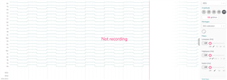
The following plot represents 21 channels of 3 ADS1298 devices, each configured for the internal test signal with gain = 6. Note the inconsistent p-p voltage of the square waves.
Register settings
/* EEG Setup for Initialization */
 ads_init_regs_confg_t eeg_c1_init_regs_config = {
 .ADS_REG_ID_DATA = 0x92,
 .ADS_REG_CONFIG1_DATA = 0x65, //LP, multiple readback mode, oscillator clock output enabled, data rate: 500Sps
 .ADS_REG_CONFIG2_DATA = 0x10, // Enable internal test signal
 .ADS_REG_LOFF_FLIP_DATA = 0x00,
 .ADS_REG_PACE_DATA = 0x00,
 .ADS_REG_RESP_DATA = 0x00,
};

 //----- Mode Setup Config ------//
/* EEG-Chip1 Read Without Lead Off */
 ads_op_regs_confg_t eeg_c1_op_read_without_lead_off_and_Z_measurement = {
 .ADS_REG_LOFF_DATA = 0xF3,
 .ADS_REG_CONFIG4_DATA = 0x00,
 .ADS_REG_LOFF_SENSP_DATA = 0x00,
 .ADS_REG_LOFF_SENSN_DATA = 0x00,
 .ADS_REG_CONFIG3_DATA = 0xC0,
 .ADS_REG_RLD_SENSP_DATA = 0xFF, // all positive channels are selected for RLD sensing
 .ADS_REG_RLD_SENSN_DATA = 0xFF, // all negative channels are selected for RLD sensing
 .ADS_REG_GPIO_DATA = 0x43, // GPIO4:output:0:parallel SW, GPIO3:output:1:series SW, GPIO2:input:0:N/A, GPIO1:input:0:QC
 .ADS_REG_CHnSET_DATA = 0x05, // Channel mux set to test signal
 .ADS_NUMBER_OF_ON_CHANNELS = 8,
};
Thanks for your help
Regards
Reid