Other Parts Discussed in Thread: INA333,
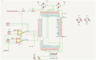
I am using three channels of the ads1298, two have an ina333 for 2 differential EEG channels as you can see EEG 1 and EEG2 referenced to the Reference electrode. The outputs connected to INP pin and the INN pin connected to AGND (analog ground) is this right? - Question 1.
The REF pin of the INA is connected to the output of RLD pin - I took this suggestion from another answer (https://e2e.ti.com/support/data-converters-group/data-converters/f/data-converters-forum/428941/grounding-problems-ads1298-ina114-and-human-test-subject) to be the effective signal ground. Is this still a good approach for the Ref Pin of INA - Question 2(a). Since the RLD pin is the effective signal ground should the INN pin on ADS1298 be connected to the RLD output instead of AGND then - Question 2(c)
Question 2(b) - Although from another question (https://e2e.ti.com/support/data-converters-group/data-converters/f/data-converters-forum/602899/tina-spice-ads1298-ads1298-without-ina-as-the-first-stage) there is a reply that mentions "If you are using a single supply, you can't connect ground to INxN. The output range of the PGA is limited to within 300 mV of the supply rails. You should instead use mid-supply as the INA's ref." Hence in this case one app engineer say to connect REF pin to mid supply than the output of RLD pin as compared to another app engineer. I am confused with these conflicting suggestions for similar applications. Similarly, what should the INN pin of the ADS1298 be connected to Ground (AGND or RLD output <effective ground>) or Mid supply?
I have connected two EOG electrodes to one channel, since the amplitude range is 50 to 3500uV which is almost similar to ECGs range I assumed that I could input them without a preamp, and just use the programmable gain is this possible? - Question 3.
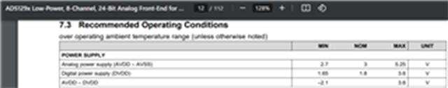
AGND - Analog ground - 0V
GNDD - Digital ground - 0V
Analog voltage and Digital Voltage - 3.3V
Are all my supply connections correct, is there anything that I have missed out? - Question 4
Can I use the ads1298 as a multimodal acquisition device as I have shown in the schematics, any potential issues that might arise? - Question 5
(forgot to include the power to INA in the schematics its 3.3V as well)
Thank you team for the continued support!