This thread has been locked.

If you have a related question, please click the "Ask a related question" button in the top right corner. The newly created question will be automatically linked to this question.

AFE4490: AFE4490 LED no woring

Part Number: AFE4490
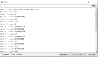
Hello, I tried to use afe4490 to measure spo2, but the LED light did not light up during the implementation. 
I have powered on the afe4490 and written it into the register, but it still has no effect.I've seen similar posts before, but I couldn't find the answer.
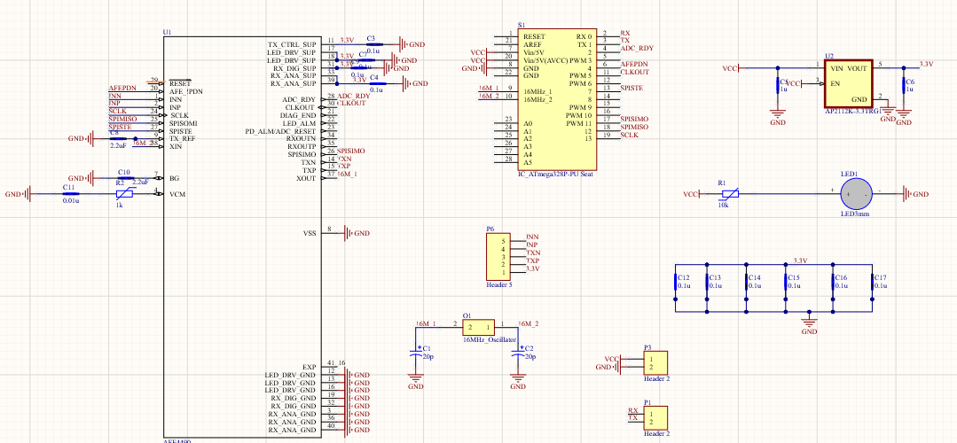
The LED I use has a common anode and is supplied with a voltage of 3.3v externally.
The other end of the LED is directly connected to the TX pin. When I do not connect the LED, the single TX pin is 0.99V and 3.3V. No voltage between TX and TX
The following is my schematic, the MCU is ATmega328PU

  • Below is the register value I set

    #define CONTROL0 0x00
    #define LED2STC 0x01
    #define LED2ENDC 0x02
    #define LED2LEDSTC 0x03
    #define LED2LEDENDC 0x04
    #define ALED2STC 0x05
    #define ALED2ENDC 0x06
    #define LED1STC 0x07
    #define LED1ENDC 0x08
    #define LED1LEDSTC 0x09
    #define LED1LEDENDC 0x0a
    #define ALED1STC 0x0b
    #define ALED1ENDC 0x0c
    #define LED2CONVST 0x0d
    #define LED2CONVEND 0x0e
    #define ALED2CONVST 0x0f
    #define ALED2CONVEND 0x10
    #define LED1CONVST 0x11
    #define LED1CONVEND 0x12
    #define ALED1CONVST 0x13
    #define ALED1CONVEND 0x14
    #define ADCRSTCNT0 0x15
    #define ADCRSTENDCT0 0x16
    #define ADCRSTCNT1 0x17
    #define ADCRSTENDCT1 0x18
    #define ADCRSTCNT2 0x19
    #define ADCRSTENDCT2 0x1a
    #define ADCRSTCNT3 0x1b
    #define ADCRSTENDCT3 0x1c
    #define PRPCOUNT 0x1d
    #define CONTROL1 0x1e
    #define SPARE1 0x1f
    #define TIAGAIN 0x20
    #define TIA_AMB_GAIN 0x21
    #define LEDCNTRL 0x22
    #define CONTROL2 0x23
    #define SPARE2 0x24
    #define SPARE3 0x25
    #define SPARE4 0x26
    #define SPARE4 0x26
    #define RESERVED1 0x27
    #define RESERVED2 0x28
    #define ALARM 0x29
    #define LED2VAL 0x2a
    #define ALED2VAL 0x2b
    #define LED1VAL 0x2c
    #define ALED1VAL 0x2d
    #define LED2ABSVAL 0x2e
    #define LED1ABSVAL 0x2f
    #define DIAG 0x30

  • AFE4490Write(CONTROL1, 0x000101);
    AFE4490Write(CONTROL2, 0x000000);
    AFE4490Write(PRPCOUNT, 0X001F3F);

    AFE4490Write(LED2STC, 0X001770); //timer control
    AFE4490Write(LED2ENDC,0X001F3E); //timer control
    AFE4490Write(LED2LEDSTC,0X001770); //timer control
    AFE4490Write(LED2LEDENDC,0X001F3F); //timer control
    AFE4490Write(ALED2STC, 0X000000); //timer control
    AFE4490Write(ALED2ENDC, 0X0007CE); //timer control
    AFE4490Write(LED2CONVST,0X000002); //timer control
    AFE4490Write(LED2CONVEND, 0X0007CF); //timer control
    AFE4490Write(ALED2CONVST, 0X0007D2); //timer control
    AFE4490Write(ALED2CONVEND,0X000F9F); //timer control

    AFE4490Write(LED1STC, 0X0007D0); //timer control
    AFE4490Write(LED1ENDC, 0X000F9E); //timer control
    AFE4490Write(LED1LEDSTC, 0X0007D0); //timer control
    AFE4490Write(LED1LEDENDC, 0X000F9F); //timer control
    AFE4490Write(ALED1STC, 0X000FA0); //timer control
    AFE4490Write(ALED1ENDC, 0X00176E); //timer control
    AFE4490Write(LED1CONVST, 0X000FA2); //timer control
    AFE4490Write(LED1CONVEND, 0X00176F); //timer control
    AFE4490Write(ALED1CONVST, 0X001772); //timer control
    AFE4490Write(ALED1CONVEND, 0X001F3F); //timer control

    AFE4490Write(ADCRSTCNT0, 0X000000); //timer control
    AFE4490Write(ADCRSTENDCT0,0X000000); //timer control
    AFE4490Write(ADCRSTCNT1, 0X0007D0); //timer control
    AFE4490Write(ADCRSTENDCT1, 0X0007D0); //timer control
    AFE4490Write(ADCRSTCNT2, 0X000FA0); //timer control
    AFE4490Write(ADCRSTENDCT2, 0X000FA0); //timer control
    AFE4490Write(ADCRSTCNT3, 0X001770); //timer control
    AFE4490Write(ADCRSTENDCT3, 0X001770);

  • You may have to take several steps back.
    Do you have AFE4490EVM and GUI?
    here are some suggestions
    Check&compare your schematic with the AFE4490EVM schematic to make sure no significant errors/mistakes.
    If above is correct, after power up, please check all the power rails are correct.
    Then, did you follow the correct Supply Ramp sequences and the reset sequence and Register Initialization in the datasheet?
    Make sure you connect the LEDs in the correction orientation.
    Dose your power supply supply enough voltage for the LEDs?
    Are you able to write and read back register settings correctly?

    After above are achieved, then load the EVM GUI's default register configurations to your system, if everything is correct, you should see some LED light up.

    Thanks.

  • I don't have AFE4490EVM ,so  maybe I can't not check everything

  • Hi,

    You can still find the AFE4490EVM schematic in user guide and download the GUI, which has default register configurations.

    https://www.ti.com/tool/AFE4490SPO2EVM

    And study that default configurations with datasheet and load the default register configurations to your system to do some comparison.

    Thanks,

  • Thans.I will try

  • Hello Ting,

    I will close the post for now. Let us know if you have any further queries.

  • Hello, when I want to confirm whether the output voltage of each pin is correct first, when I measured the TX_REF and BG pins, I found that its voltage value will gradually weaken from 1v, but the TX_REF I set should be 0.75 v, I would like to ask why he continues to be weak

  • Hello,

    The BG and TX_REF voltage will be stable. It shouldn't drop or gradually weaken.

    Check the board for supply ground impedance to look for any possible supply ground short or faulty capacitor. 

    You will need to monitor the current drawn by the AFE4490 device on your board and confirm if the current matches with the datasheet.

  • hello,Praveen Aroul

    my LED is working right now,althought the voltage still wrong.

  • Hello Ting,

    Kindly share complete details of the issue to help with the debug.

    how is the led working now? What did you do differently this time around? Which voltage level is not correct?

  • hello,

    I changed the control2 value in the loop from 0x02 to 0x04, and reset the reset before initializing the AFE4490.

  • Hello Ting,

    Is your issue resolved? Sorry the information you are sharing is not sufficient to understand the issue and help with the debug.

  • hello,

    It's ok.but now I facing another problem,I recive data from diode,but even I don't put my finger on the led and photodiode,I still get data just like the picture shows below

  • Hi,

    your schematics shows 16MHz crystal feeding into the AFE. The device requires 8 MHz crystal. please check the datasheet for additional details. The operation of the device cannot be guaranteed with your clock configuration.

  • hello

    I forgot to revise the mark,but actully what I use is 8Mhz,and I can get 4Mhz form CLKOUT pin

  • Hello,

    Follow the guidelines mentioned in the FAQs #7 and 9 in the below link for sign of life and board bring up.

    https://e2e.ti.com/support/data-converters/f/73/t/369445

    Please verify if the written registers are read back correctly.