This thread has been locked.

If you have a related question, please click the "Ask a related question" button in the top right corner. The newly created question will be automatically linked to this question.

ADS1248: Thermopile Used with ADC

Part Number: ADS124S08
Other Parts Discussed in Thread: ADS1248

Hello, 

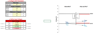
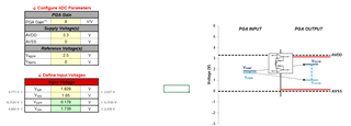
I have a thermopile sensor that gives min-max output between 0.134 mV and 178 mV. I used the ADS124S08 integration and gave the output of the thermopile directly to the ADC integration.

When we talked about this issue before, I found gain=16 V/V, but now I am not sure about this value. Because with this gain, the thermopile min-max value does not stay in the appropriate range and is not correct.

My question to you;


Can you give me a gain value that I can use in the software, taking into account the min-max range of the thermopile? With calculations, of course.

  • Hi Gulbahar G

    Are you using the ADS124S08 or the ADS1248? You mention one in your thread title and another in the body of your post

    You will have to be more specific with respect to how the gain affects the thermopile measurement. What values are you getting from the ADC, and what values do you expect to get? Note that the ADC has error and noise, so the output will only be stable to the extent that those parameters allow

    Please provide data, scope shots, etc., to help us better understand what is happening with your system. Please also provide your register settings

    -Bryan

  • Hello, Bryan,

    I'm using ADS124S08 as the ADC. Sorry for the confusion.

    Let me explain it from the beginning then. The min-max output value of the thermopile is between 0.134 mV and 178 mV.

    I need to increase this mV value to the ADC reading range with the PGA in the ADS124S08 integration so that the accuracy is high.

    If we look at the datasheet of the integration, in the "Functional Block Diagram" image, the incoming signal first enters the PGA and then the ADC.

    I have a problem in calculating the gain required to raise the signal to the ADC range.

    Again, I make my calculations with reference to "Equation 5" in the datasheet, but VoutN always comes out "-". This does not provide the range of 3.15V to 0.15V from AVDD=3.3V and AVSS=0V which should be provided for me. Also Vref=2.5V.

    While doing this calculation, I also used a "ADS1x4S0x Calculators: Common-Mode Range Calculator" and when I enter the data there, I always drop "-" when I enter gaini 16 or 32 and as I said, this does not provide the ADC reading Voltage range.

    I have attached the document I made the calculation.

    Can you please show me a way? What am I doing wrong.

    ADS1x4S0x Design Calculator.xlsx

  • Hi Gulbahar G.,

    The first issue you have is that the gain is too high. If you are using VREF = 2.5V, then the max voltage you can apply using a gain of 32 is 2.5V / 32 = 78mV. So your 178mV signal will overrange the PGA. You can always look at it the opposite way: 2.5V / 178mV (your max signal) = 14.04, which is the maximum gain you can use for this signal. Since the ADS124S08 does not have a gain of 14, you would need to select the next smallest option, which is a gain of 8

    This solves one issue, but you can see that there are still errors. The next issue is that you are violating the ADC PGA common-mode range. VINP and VINN are the absolute voltage on the input pin of the ADC. So if your thermopile has an output voltage of 178mV, is that a differential or single-ended voltage? If that voltage is single-ended, then VINP = 178mV and VINN = 0V. Maybe that sensor has an offset / bias voltage to shift the output to mid-scale. For example, if that offset was 2.5V, then VINN = 2.5V and VINP = 178mV + 2.5V = 2.678mV.

    Since the ADS124S08 has an instrumentation amplifier as a PGA, the input common-mode equals the output-common mode. This means your input signal should be centered on mid-supply for the ADC. If AVDD = 3.3V, that means the common-mode should be at ~1.65V. You can see from the image below that setting VINN = 1.65V and VINP = 1.828V yields a valid output, and the differential voltage is 178mV. This is how you should use the tool

    One other issue = when I opened the Excel doc, both VREFP and VREFN = 0V, which means you had no reference voltage. So the calculator was never going to work

    -Bryan