This thread has been locked.

If you have a related question, please click the "Ask a related question" button in the top right corner. The newly created question will be automatically linked to this question.

ADS1263: To measure 1uA to 15A DC current using ADS1263

Part Number: ADS1263

Hi, 

Our requirement is to measure 1uA to 15A DC current. We are planning to implement it using the ADS1263 ADC part for better resolutions.

We have below queries,

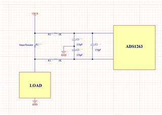
1. Is this circuit correct for implementing current sense resistor?

2. Can you provide a reference for calculating values of C1-C3 and R1, R2?

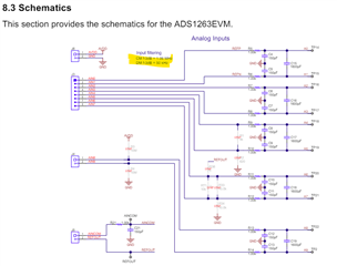
3. What is the meaning of CM f-3dB= 1.06 MHz and DM f-3dB = 50 kHz present in ADS1263EVM-PDK schematic shown below?

4. Is there any reference application document where ADS1263 is used for the current sense?

Our assumption is that using the ADS1263 part for high-side current sense in differential configuration will provide more accurate results and

measure instantaneous current changes. Please correct me if i'm wrong.

  • Hi Brijesh Yadav,

    One thing to consider before you continue: the faster you sample, the more noise will be introduced into your system. For example, the ADS1263 is effectively a 16-bit ADC at the highest data rate (38kSPS). So if you want to sample at 38 kSPS, you might be better off with a different ADC. Measuring "instantaneous current changes" sounds like you want to sample very fast, which is not really the use case for the ADS1263

    Here are some general recommendations about how to size the filter R and C: https://e2e.ti.com/support/data-converters-group/data-converters/f/data-converters-forum/955466/faq-delta-sigma-adc-anti-aliasing-filter-component-selection

    What is the VBUS voltage? The voltage applied to the ADC must be less than that required by the Recommended Operating Conditions table. If VBUS <= 5V, this should be okay.

    -Bryan

  • Hi Bryan,

    Thank you for your reply.
    We have a few assumptions please let us know if these are correct,
    1. -Vref for full-scale differential input voltage is managed by ADS1263, i.e. we don't need to provide it externally.
    2. As our application is battery profiling, and ADS1263 has a Full-scale differential input voltage range of –VREF / Gain to VREF / Gain, ADS1263 will be suitable for measuring bidirectional current.

  • Hi Brijesh Yadav,

    1. -Vref for full-scale differential input voltage is managed by ADS1263, i.e. we don't need to provide it externally.

    Did you mean to add the "-" sign in front of "Vref"? If so, do you think you need a negative reference for this board?

    If not, the ADS1263 has an internal 2.5V reference. The ADS1263 also has external reference inputs if the performance of the integrated VREF is insufficient for your application

    2. As our application is battery profiling, and ADS1263 has a Full-scale differential input voltage range of –VREF / Gain to VREF / Gain, ADS1263 will be suitable for measuring bidirectional current.

    This depends on the absolute voltage of your input signals. If VREF = 2.5V and G = 1, then you can measure from -2.5V to +2.5V differentially. That means the differential voltage between the AINP and AINN pins (VIN = AINP - AINN) is between those two voltages

    But the absolute voltage on any pin must be within the range provided in the Recommended Operating Conditions. So if your absolute voltages are AINP = 20V and AINN = 17.5 V, then that is way outside the range of the ADC. But the differential voltage is 20-17.5V = 2.5V. So you need to be careful about the absolute voltages as well as the differential voltages.

    You will need to read the entire datasheet to really understand how this ADC behaves.

    -Bryan

  •  , Thank you for the confirmation over the differential range , The planned shunt value is 10mohm to sense the DC current which will provide current sensing range of 27uA to 250A based on the Reference 2.5 and configuration "Gain = 32 , Sample Rate = 4800 SPS , Filter Mode = Sinc4, ENOB (5V Ref) = 21.7, ADC Noise 0.277 uVrms".

    our application is to sense from several uA to around 12-15A DC current using this setup as indicated earlier by Brijesh.

    1) Now the query is sensing this current on Low side and in single ended configuration is desired? or to sense current in High side and with Differential configuration is more suitable? (We do not have the load short detection requirement, so please suggest which mode is accurate and more suitable to our application using this ADC part?

    2) as brijesh already shared a high level diagram of the architecture to sense the current, can you please suggest if any parts are required to have on board for this complete setup which we might have missed to add.

    3) we have requirement to monitor complete system input current from input USB, and battery charge discharge currents using this ADC ic, so can we use 2 different shunts on the different ADC channel of ADS1263? we will require to add the switching mechanism and the sampling rate for both channel will get affected by this switching time require to change the channel in ADS126x, is my understanding correct?

    Thanks for all the efforts you are making to solve our queries.

  • Hi,   Did you get a chance to look into the queries shared by my colleague?

  • Hi Brijesh Yadav,

    1) Now the query is sensing this current on Low side and in single ended configuration is desired? or to sense current in High side and with Differential configuration is more suitable? (We do not have the load short detection requirement, so please suggest which mode is accurate and more suitable to our application using this ADC part?

    I provided you guidance to answer this question in my last response, did you not get it? I discussed the difference between differential and absolute voltages, and how to calculate them. This is the answer to your question

    Differential measurements are generally better for rejecting common mode noise, but only if they meet the requirements I specified in my previous response

    we have requirement to monitor complete system input current from input USB, and battery charge discharge currents using this ADC ic, so can we use 2 different shunts on the different ADC channel of ADS1263? we will require to add the switching mechanism and the sampling rate for both channel will get affected by this switching time require to change the channel in ADS126x, is my understanding correct?

    What do you need a switching mechanism for? I assume these are two completely different current measurements, no?

    The ADS1263 has an internal mux, so you would connect one shunt to one differential input channel and the other shunt to another differential input channel. Then you will just switch the mux to measure the different shunts, which can be completed via commands to the register map

    Yes, the amount of time to sample will be affected by switching the ADC mux. See Table 9-13 in the datasheet for more information about conversion latency

    Again, I will reiterate: please read the entire datasheet to really understand how this ADC behaves. Many of these questions are answered either directly or indirectly in the datasheet.

    -Bryan