This thread has been locked.

If you have a related question, please click the "Ask a related question" button in the top right corner. The newly created question will be automatically linked to this question.

TSW1400

Other Parts Discussed in Thread: TSW3085EVM, DAC3482, LMK04806, LMK04808, ADS5402

Hello,

i use a TSW1400 with a TSW3085. Are there sample Files ( LTE GUI ) for the TSW1400 availible ,  such they exist for the TSW3100? 

IN the High Speed DAte Converter Pro i can load some sample Files. But all sample Files have an offset from 30 Mhz to the LO. How can i create such Files?

When i create inthe Gui with " I/Q Multitone Genarator" some Signals i have always this 30 MHz offset. Or is the only way to use an offst  -30 MHz from Carrier. My aim is to have a noisy  or real LTE Signal in the adjacent Channel in the  LTE enviroment.

Thanks for answers.

Martin


  • Hi Martin,

    The pattern generators for LTE, WCDMA, etc can be found on the TSW1400EVM web folder page. There are two download links for either WINXP or WIN7 system. 

    WinXP

    http://www.ti.com/litv/zip/slwc111

    Win7

    http://www.ti.com/litv/zip/slwc110

    You can program your own offset and bandwidth of the signal, and the tools will generate the .tsw file for your to load into the HSDCPro software.

    -KH

  • Hi Ti,

    I am planning to buy TSW 1400 EVM.

    Does this EVM have Matlab drivers ?

    Has anyone tested the data capture and transmit from EVM to PC over USB?

    thanks

    Venky

  • Hello Venkatesh,

    The latest version 2.1 software includes new examples and .dll libraries for you to try out. The latest software can be downloaded at:

    http://www.ti.com/litv/zip/slwc107e

     Once you install the software, the library is located at:

    C:\Program Files (x86)\Texas Instruments\High Speed Data Converter Pro\HSDCPro Automation DLL

     There are Matlab examples and Labview examples.

    -KH

  • KH,

    Thank you and I looked at the examples.

    1. Is there a way to write the ADC output samples into a matlab buffer instead of a CSV file ?

    I dont see that option in the documentation.

    -Venky


  • Hi Venky,

    We do not have the option to save as a matlab buffer. However, you can easily load the csv file into Matlab using the code below:

    data = dlmread('filename.csv');

    This will load the CSV file ('filename.csv') into the variable "data" that will have dimensions [num_samples x num_channels].

    Regards,
    Matt Guibord 

  • Hi Mat, 

    1. How long does it take to to download 2 channel of 256K samples each ?

    2. How long does it take to upload the same?

    3.In the HSDC API doc file the recommended timeout is 30 sec and for firmware download it is more.

    Is the timeout ( 30 sec ) here a generic high value or a must have for all functions ?

    Above questions are centered around the simulation time.

    thanks

    Venky

  • Any update on this question ?

    thanks

    Venky

  • Hi Mat,

    I got the TSW1400 EVM pattern generator card.

    I want to generate multitone patterns and I looked at the slwu082.pdf that talks about this topic.

    Installed the MCRinstaller from Mathworks.

    ----------------------------------------

    Question:

    ----------------------------------------

    1. Where can I find TSW1400 MultiTonePattern program ?

    I don't find it in my HSDC pro installation folder 

    C:\Program Files (x86)\Texas Instruments\High Speed Data Converter Pro

    thanks

    Venky

  • Hi Venky,

    The multi-tone generator is built into HSDC Pro. If you open HSDC Pro and click on the "DAC" tab, you'll see the generator in the bottom left corner of the GUI.

    Regards,
    Matt Guibord 

  • Yeah see that and I am able to use it.

    Can you point me to TSW1400 CommSignalPattern program please ?

    thanks

    Venky

  • Venky,

    The pattern generators for comm-signals are available on the TSW1400 product page (below) under the software header. It is listed as "XP GUI software for use with the TSW1400 Pattern Generator User's Guide". There is also a windows 7 version listed.

    http://www.ti.com/tool/tsw1400evm

    Regards,
    Matt Guibord 

  • Matt,

    Thanks . I was able to use the PC program to generate patterns.

    Is there a way I can convert *.tsw file to *.csv file  on PC ?

    Venky

  • Hi Venky,

    We do not have a way to convert the .tsw file to a .csv. This was done to prevent the files from being used for non-TI related evaluation.

    Regards,
    Matt Guibord 

  • Mat, 

    I am interested in buying TSW3085EVM.

    Will TSW3085EVM ( DAC EVM ) work with TSW1400 EVM ?

    thanks

    Venky

  • Hi Venky,

    Yes, the TSW3085EVM will work with the TSW1400.

    Regards,
    Matt Guibord

  • Hi Matt, 

    I connected the TSW3085 EVM to TSW 1400 EVM and made sure the jumpers on 3085 are configured as in the user guide and loaded the registers using 3085 evm UI

    When I click on DAC , the tsw1400evm asked if I need to update the firmware.

    I selected DAC3482 and selected ok

    "The Downloading Firmware status never completes."

    I have not fed any RF LO clock input to the DAC EVM.

    I guess download firmware is a basic step.

    Am I missing something ?

    Please advice.

    thanks

    Venky

  • Hi Venky,

    Make sure the USB is connected. This is done through the "Instrument Options" menu. Try disconnecting and reconnecting to the TSW1400. Secondly, make sure the board is actually powered on. You can connect to the board if the FPGA does not have power. You'll need to flip the power switch after supplying the 5V power supply. You'll know that the board is on when the fan is running.

    Please let me know if you're still having difficulties. There may be a software issue.

    Regards,
    Matt Guibord 

  • Mat,

    Forgot to respond to my post.

    Have it working now.

    When I received the board one of the jumpers was 1-2 instead of 2-3 on the DAC EVM.

    Probably the connection was bad between the two evms.

    thanks

    Venky

  • Hi Venky,

    Great, thanks for the update.

    Regards,
    Matt Guibord 

  • Hi Matt, 

    I tried running the tsw1400 and TSW3085EVM following slau374.pdf user guide ( section 3.5 )

    Configured the DAC using the file DAC3482_1228p8MHz_2xInt_NCO_30MHz_single_sync_source_mode.txt as in document.

    Selected WCDMA_TM1_complexIF30MHz_Fdata614.4MHz_1000.tsw in the TSW1400 GUI. I do see the FFT as expected.

    Problem:

    I see a -38dBm output on SA but occupied BW is only 65 KHz . This is a bell shaped output.

    I don't get an expected result as shown in page 23 of slau374.pdf. 

    Toggling the RF input LO ( 1780MHZ ) I see this signal toggling.

    Am I missing anything ? 

    Please advice

    thanks

    Venky

  • Venky,

    You mentioned that you changed one of the jumpers from 1-2 to 2-3 position. Could you let me know which jumper you have changed? Please make sure TXENABLE jumper is pulled high for valid data transmission.

    For the TSW3085EVM GUI, after you finished loading the .txt configuration file, please press "send all". Please check to see if the LMKLOCK (D7) is lit or not. If everything is configured correctly, the LED will stay lit. 

    For the HSDC PRO GUI, after you load the TSW1400 firmware and signal source file, could you check to see if you pressed the "send" button (beneath the DAC selection menu). This will transfer the signal data into the DAC.

    -KH 

  • Kang, 

    tsw3085 evm is Rev D

    Reference : slau374a.pdf. page 19 - table3

    I modified JP1 from 1-2 to 2-3. I tried setting it back but not change.

    LMCLOCK LED is lit after I load the registers and press the send button.

    Yes. I selected the waveform and pressed the Send button in TSW1400 EVM

    I also followed the youtube video in the link to double check my procedure

    http://www.youtube.com/watch?v=Rqh6zH86mdw

    My observation :

    1: Looks like the input LO that we feed is attentuated and sent as RF Out as I just observe a bell shaped ( sync function ) on SA.

    If input is 0 dBm the output I see is ~ 40 dBm.

    May be the modulator is not working ?

    2.  Also the tsw3085evm board is Rev D 

    I don't see the DAC configuration files in the directories below 

    C:\Program Files (x86)\Texas Instruments\TSW308x\Configuration Files\TSW3085_16bitLVDS_2Channels\RevC ,REVA and REVB ( No Rev D??)

    Could this be an issue?

    3. Going by video and the application note assuming the DAC is fed by internal clock.

    Please advice.

    thanks 

    Venky

  • Hi Venky,

    Even though the LO input to the modulator is at 0dBm, you should see attenuated LO frequency at the modulator output. Ideally, the modulator should not have any LO feedthrough at all. The LO frequency is generated by the overall DC offset from both the DAC output and modulator baseband input. -40dBm of LO feedthrough sounds about right.

    I am not sure the reason that the LO tone at the RF output is bell shaped. Could you plug in your LO generator directly to the signal analyzer to see if the same thing occurs? I suspect that there are noise coupled onto the LO generator.

    The DAC3482 output is centered at 60MHz. The baseband WCDMA file is centered at 30MHz, and the DAC3482 has internal NCO fine mixer enabled at 30MHz. The 5MHz wide WCDMA file should be 60MHz away from 1.78GHz, creating the final RF output at 1.84GHz.

    Could you go to the Advanced tab of the TSW308x GUI and click on the "Clear Status' button and check the alarm status? This could perhaps narrow down the issue. Also, if you can provide some screenshots of the HSDC PRO GUI, TSW308x GUI, and the spectrum capture, I will take  a look and see if we are missing something. 

    The config file for rev C will work with rev D of the TSW3085EVM as well. 

    Thanks.

    -KH

  • Kang,

    Please find the ppt with the GUI and IN/Output waveforms

    I do not see any red flags in the Alarm section.

    Let me know if I am doing something incorrect.

    3630.totidebug.pptx

    thanks

    Venky

  • Venky,

    Just to confirm, you did not see any waveform at 1840MHz? 

    Also, did you adjust the NCO of the DAC by any chance? I did not see the digital section and advanced section of your GUI. I just want to make sure that the signal is not located somewhere else due to adjustment of NCO settings.

    If you can provide a broader spectrum of the RF output, it will be helpful.

    -KH

  • Kang,

    I am attaching the updated slide set with all tabs and full spectrum.

    No I dont see any signal at 1.84 Ghz.

    3718.totidebug.pptx

    Thanks

    Venky

  • Hi Venky,

    I would like to ship you a new set of hardware that I have tested just to make sure this is not a hardware issue. I can private message you offline for your information.

    Thanks

  • Hi Kang,

    Thank you for the HW.

    If you would like me to come down to TI I can. I am local in Richardson.

    Venky

  • Hi TI,

    I using the DAC 3085 evm along with TSW 1400 evm.

    The input is a complex LTE waveform.

    LO is 1960Mhz 

    DAC 3085 EVM is externally referenced with a 10 Mhz input.

    Attaching a ppt with Spectrum analyzer output.

    Problem : 

    The spectrum on the GUI is fine .

    I see skirting on the spectrum as shown in the ppt. 

    Questions:

    1.What is the reason for this behavior in the DAC 3482?

    2. How can I avoid it in the DAC environment?

    Thanks

    Venky

    2626.toti.pptx

  • Hi Venky,

    The output waveform with the skirting seems to be the data not being coherent at the DAC input (i.e. the value at the starting of the pattern does not match the ending of the pattern). You may want to consider creating a coherent signal or applying windowing function to the waveform.

    The waveform is 1001 pattern. The left hand side of the pattern seems to be fine. Did you generate the two patterns independently and then summed up later? 

    If the skirting issue is due to the DAC's phase noise or the clock driver's phase noise, I would expect the skirting to apply to both carriers. 

    -Kang

  • Hi KANG

    Thanks for the suggestion.

    This was due to DAC preamble ( 32 ).

    I made it 0 and got a sharper spectrum.

    Venky

  • Hello  TI, 

    I need to change the sampling rate of the DAC and ADC to 245.76Msps.

    The following boards have internal VCXO of 122.88Mhz

    EVMs are :

    DAC : tsw3085  with LMK48XX

    ADC : tsw1266 with LMK 4803 

    At the moment my set up runs @ 307.2 Msps

    -----------------------------------------------------------------------------------

    Questions :

    -----------------------------------------------------------------------------------

    1. Can I achieve this on the existing set up ? May be a divider of 5. If so please share the configuration file.

    2.How can I connect an external clock source to these evms to achieve 245.76 Msps sampling rate on DAC and ADC? 

    3. Any recommendation on external clock source ?

    4. Can someone share the relevant application note ?

    thanks

    Venky

  • Hello TI,

    Can someone share instructions on changing the sampling rate to 245.76 Msps please ?

    My 307.2 msps DAC/ADC is functional.

    thanks

    Venky

  • Hi Venky,

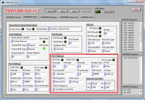
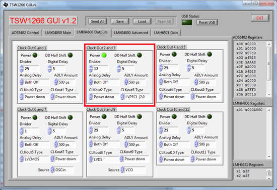
    I can answer for the TSW1266. I'm not sure which clock mode you're using (Single Loop, Dual Loop, etc), so I'll just show you what needs to change from your current setup. For the the TSW1266, simply set your LMK PLL2 settings as below to set the VCO frequency to 2949.12 MHz.

    And the clock output as a divider of 12 for 245.76 MHz out.

    If you want to use an external clock source, then you can simply load the "external_clock" configuration file that was included with the TSW1266 software.

    Regards,
    Matt Guibord 

  • Hi Matt,

    Yes. This works and I see the PLL locked on TSW1266.

    I was using dual loop.

    DAC:

    Can someone give the settings for TSW3085 to output 245.76Msps ?

    thanks

    Venky

  • Hi Venky,

    thanks for the reminder and apologies for the delay.

    You are asking for the 245.76MSPS data rate, and with 4x interpolation, the final DAC update rate is 983.04MSPS.

    The TSW3085 has the on-board LMK04806 (VCO range of 2370MHz to 2600MHz) and does *not* support the 983.04MSPS range in PLL2 synthesizer mode

    With the current setup, you will need to feed a 938.04MSPS clock directly to the CLK1 input of the TSW3085EVM and use the LMK04806 as clock buffer mode. See attached for example setup.

    To configure the TSW3085 with the LMK in PLL2 mode, you will need to swap the LMK04806 with LMK04808. The VCO range of LMK04808 supports the 983.04MSPS operation.

    -Kang

  • Hi TI,

    I am seeing unwanted signal close to center frequency @ 1955Mhz

    Please find the ADC output in the ppt attached

    Use case : Capturing the ADC data with RF input from Signal Generator.

    The setup uses TSW 1400 --> TSW1266 ( ADS5401-9)

    1955Mhz ( RF in ) --> TSW 1266 EVM

    RF LO is 2267.2 Mhz 

    ADC output sampling frequency is 307.2 Mhz 

    ADC input target frequency is 312.2 Mhz

    Questions :

    How can I get rid of the unwanted signals ?

    Could it be oscillator phase issues or any other filter parameter that needs changes ?

    7446.toti.pptx

    Note : DAC is not used here.

    thanks

    Venky

  • Hello TI , 

    After reading ADS5402 document I see that auto correction flag is disabled by default.

    After enabling , I see SNR improve from 29dB to 49 dB and improvements in SFDR as well.

    Question : 

    I read the following in SLAS936A–MARCH 2013–REVISED AUGUST 2013

    "The auto correction function yields best performance for input frequencies below 250MHz. For input frequencies
    greater than 250MHz it is recommended to disable the auto gain correction loop."

    My FIN is 307.2 Msps  and using the ADC in non interleaved , 2 channel mode ( I , Q )

    Questions :

    1. What is the meaning of this comment ?

    2. Any implications other than power ?

    3. Can this algorithm be further fine tuned for my application ?

    thanks

    Venky