


We use ADS1298RECGFE-PDK to detect ECG signals, and then we use ADS129xECG-FE software to capture signals as follows: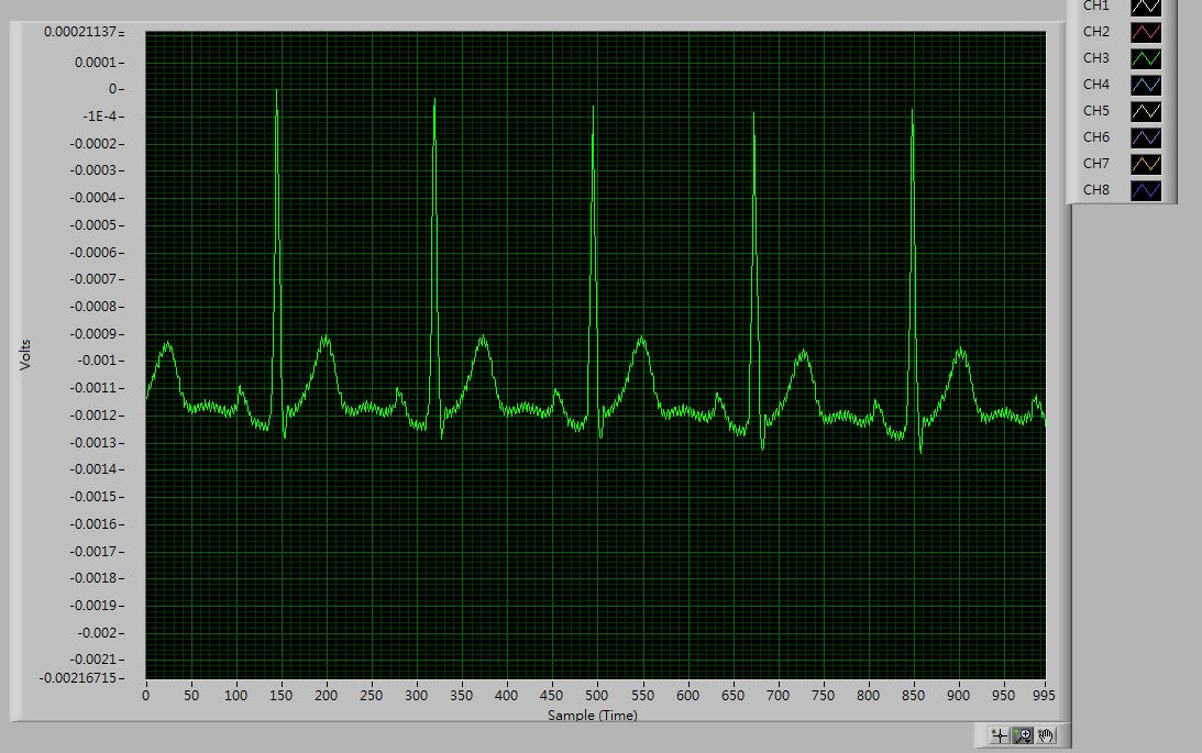
We can clearly observed the P and T waves by using 250 SPS data rate(Low Power Mode) and display the result in 1000 samples.
Then we remove MMB0 motherboard and use FPGA board to provide power, the connection of power supply is according to this page ( ). Then we use FPGA board to capture ECG signal from the SPI output of ADS1298R ECG board. We run the ADS1298R ECG board in RDATAC mode, and the timing diagram is as follows:
We need CH3 (LEAD II) ECG signal, and the timing diagram of capturing CH3 (LEAD II) data is as follows: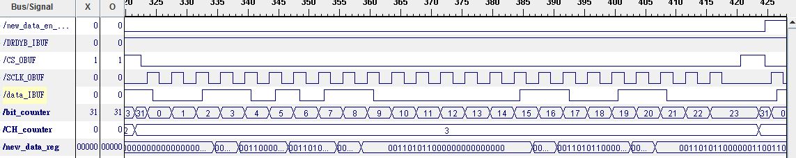
We are sure that the way we decode SPI is correct, but we captured the waveform which is shown below:
We found that the waveform has significant shake (especially P and T wave of ECG signal), but the waveforms displayed by computer software ADS129xECG-FE is much smoother and clearer. We use the same ECG electrodes to connect with ADS1298R ECG board to capture ECG signal by computer software and our FPGA.
We want to ask that whether the computer software ADS129xECG-FE do any process before display the ECG waveform or not, or why the output waveforms form computer software and our own way are such different.