This thread has been locked.

If you have a related question, please click the "Ask a related question" button in the top right corner. The newly created question will be automatically linked to this question.

ADS131E08: ADS131E08

Part Number: ADS131E08

 I´m working with the ADS131E08 using SPI to communicate with stm32f765IG  and after correctly configuring the device and start conversions

1. initialization procedure is performed in accordance with the datasheet
2. ID Control Register = 0xD2
3. Config3 = 0xCC
4. All the available commands are executed correctly
5. Output data rate <= 16 kHz, 24 bit mode

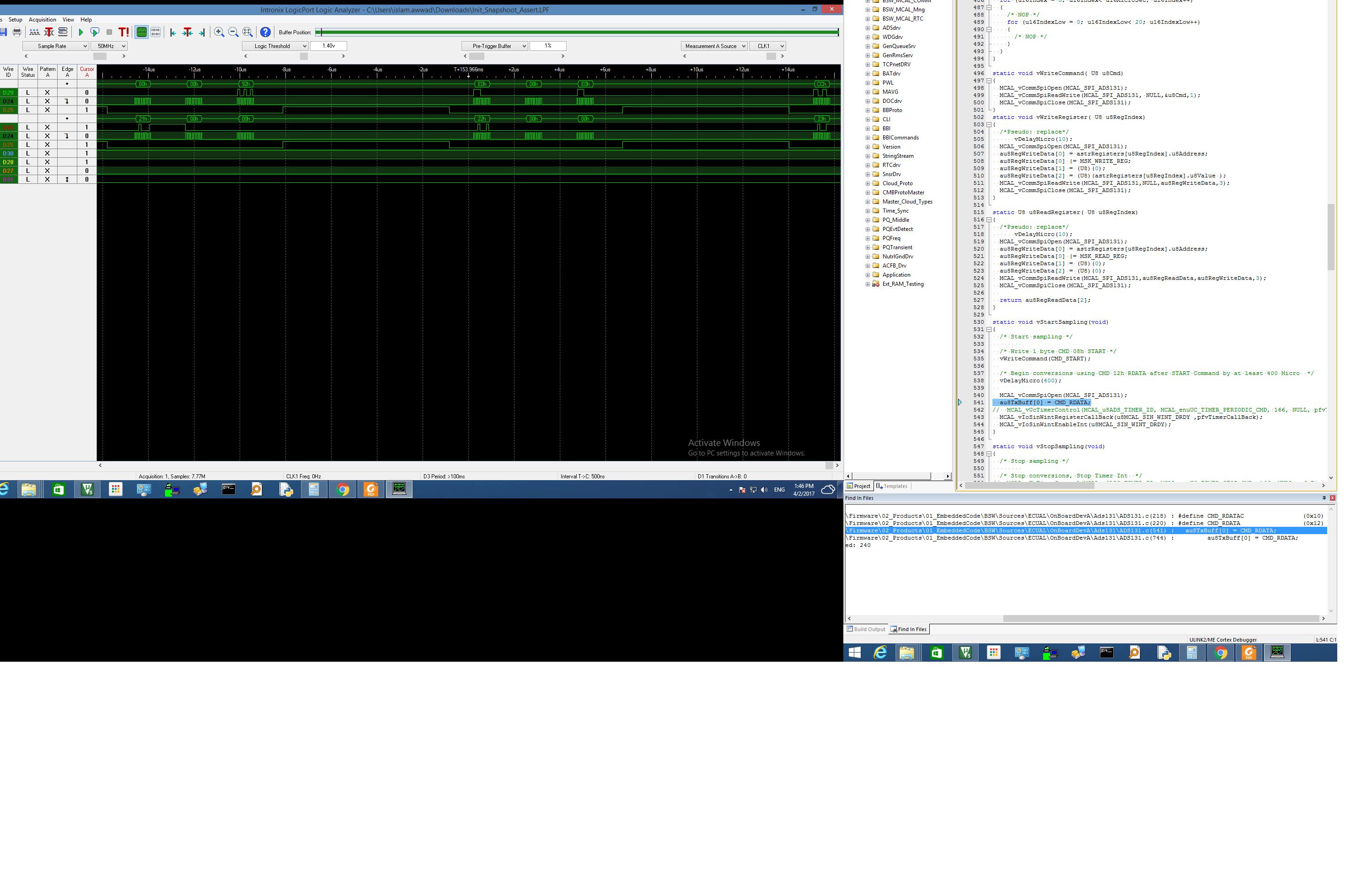
i experience a deterministic  issue which is i expect to receive values in my buffer these values are {0xD2,0xB2,0xE0,0xCC,0x00,0x10,0x10,0x10,0x10,0x10,0x10,0x10,0x10,0x08,0x00,0x00}

if(au8Registers[u8Index] != astrRegisters[u8Index].u8Value)

{

/*

rest of the code

*/


}

but the ADS chip doesn't send back these values in a definite time sometimes i wait for a long time to get the data red properly .

if i changed the spi clock to any value but 5.6 MHz i dont get the values ever .

the chip doesnt respond as it should be even when am performing the configuration in accordance to the data sheet and its not deterministic

please help me  

  • Hello Islam,

    Please post a screen capture of a logic analyzer or oscilloscope capturing the SCLK, CS, MISO, and MOSI signals during a register read.

    Regards,

    Brian

  • I've done the power up sequence just as the data sheet and the only difference is i don't read continuously i use the  CMD_RDATA command after i set the chip select pin low.

  • Hey Islam,

    This sequence looks fine. In fact, You can see the correct register values being output from the chip on the third byte of each command sequence. Does this screenshot display the issue you are having?

    Brian
  • the problem is not in reading !!

    its the time taken by the ADS chip to read the values is not constant it takes a while till it successfully reads

    is this normal

  • Hello Islam,

    I apologize I did not initially understand your question. You are saying that even after waiting the required time for startup, the device does not report the correct register values until some time later.

    I know you said that you did what the datasheet recommends during startup, but there could be other factors that could prevent the startup from occurring correctly. For example, if the analog supplies do not ramp quickly, the 2^18 clock cycle waiting period may not really begin until well after you microcontroller begins counting. Have you verified the power supply timing on an oscilloscope? Perhaps try to recreate Figure 65 with your setup.

    Regards,
    Brian