This thread has been locked.

If you have a related question, please click the "Ask a related question" button in the top right corner. The newly created question will be automatically linked to this question.

DAC161S997: DAC161S997 Grounding and EVM Component Question

Part Number: DAC161S997

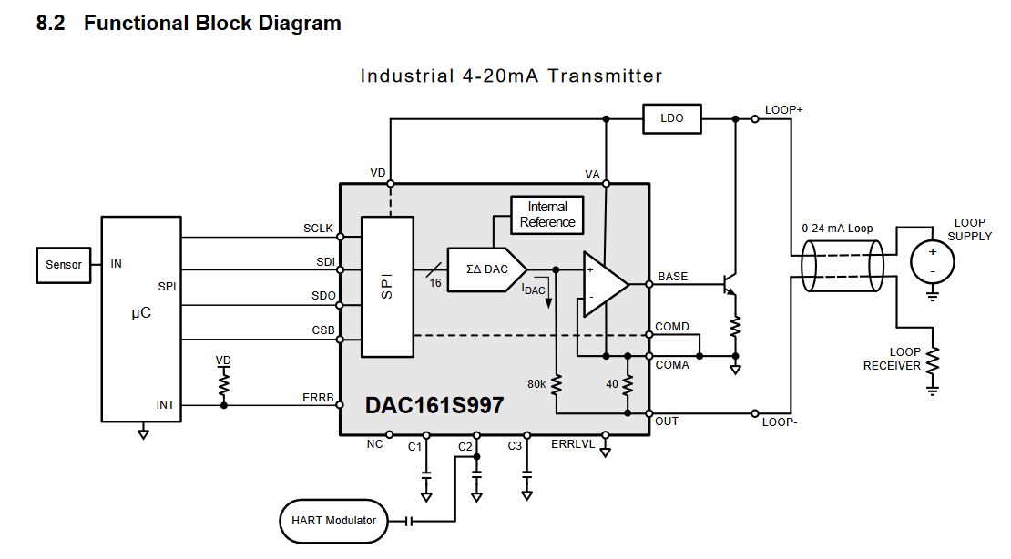
Ref doc: SNAS621A-June 2013-Revised December 2014

Loop powered schematic:

- When DAC is in Loop-powered mode (Figure 15) 

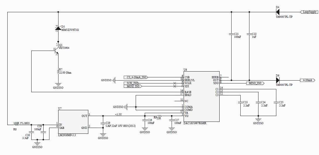
The loop instrument and the DAC grounds are isolated. Even though the potential across loop supply and it's own ground is 5V, the potential difference at the input of the voltage regulator and it's ground (LM2936MP-3.3) is less than 3V, so the DAC is not even powered ON.

- When DAC is in Self-powered mode (Figure 16)

If we try to output current greater than 16mA, we get a loop error.

How to resolve these issues?

  • Raghuveer,

    What is the load impedance that the design is driving? What is the loop supply voltage being provided?

    What exactly is meant by "the potential across loop supply and it's own ground"? Can you specifically assign net-labels to this measurement or describe exactly how the supply is being connected?
  • The load impedance(loop receiver) is 250ohms.

    By "the potential across loop supply and it's own ground", I mean the voltage source (labelled as "loop supply" in functional block diagram) and it is 5V.

    The potential difference between "LOOP+" and "COMA" (ref: functional block diagram) is less than the LDO's required input.

    The potential difference between "COMA" and "loop supply" ground is not constant.

  • Raghuveer,

    In general a 5V loop supply is not sufficient for loop powered designs as a 5V potential will be developed across the 250 ohm resistor with typical full-scale 20mA current flow. Even though the LDO / DAC are not powering up, it appears that some current is flowing through the loop, and through the load resistor, which is decreasing the supply voltage available for the LDO. Perhaps some simple experiments would be to increase the loop supply voltage, or to reduce the loop resistor. At least in this case we can see if the system can start-up on it's own and validate that there's no other unexpected ground loops in the design.

    In the self-powered case, what is the supply voltage being provided to the device?
  • When LDO and DAC aren't powered up, there is no current through load resistor.

    Increased the loop supply voltage to 12V (Cannot change the load resistance). With 12V loop supply the system cannot go beyond 19.5mA (in both self powered and loop powered mode)

    We have checked with another instrument which has a loop supply voltage of 36V and with it we were able to obtain 0-24mA range.

    In self-powered mode LDO input is 5V and DAC input is 3.3V

    Thank you for your help.

  • Raghuveer Kasaraneni said:
    When LDO and DAC aren't powered up, there is no current through load resistor.

    In this case I assume you have still applied power to the system? What I intended to communicate was that the LDO does not appear to be starting up if there is insufficient input voltage for it to establish regulation, however it would seem there is some path for current to flow which is leading to a voltage drop across the load resistor which is eating into the overall headroom.

    Of course with no supply enabled, there is no current flow.

    Raghuveer Kasaraneni said:
    Increased the loop supply voltage to 12V (Cannot change the load resistance). With 12V loop supply the system cannot go beyond 19.5mA (in both self powered and loop powered mode)

    Is this 19.5mA value the current measured through the loop with an ammeter? What was the voltage on the load at the same time?

    Raghuveer Kasaraneni said:
    We have checked with another instrument which has a loop supply voltage of 36V and with it we were able to obtain 0-24mA range.

    What specifically does this mean? You gave the system a 36V supply?

  • Hello,

    Do you have any updates on this thread or responses to the above questions?
  • Kevin Duke said:

    Is this 19.5mA value the current measured through the loop with an ammeter? What was the voltage on the load at the same time?

    It is measured using a digital multimeter. The voltage on the load is 5.1V.

    Kevin Duke said:

    What specifically does this mean? You gave the system a 36V supply?

    Yes, we gave a loop supply equivalent to 36V instead 12V.

    We have decided to use self-powered mode.

    Observations:

    • The ground of loop supply is not connected to COMA/COMD
    • When loop supply = 0V
      • VA - COMA = 3.3V

    • When loop supply = 12V and DAC setting is for 20mA
      • VA - COMA = 4V
      • loop supply - COMA = 5.3V
      • load current = 19.5mA
      • voltage on load = 5.1V
      • BASE -COMA = 1.12V