This thread has been locked.
If you have a related question, please click the "Ask a related question" button in the top right corner. The newly created question will be automatically linked to this question.
I'm trying to get my ADS131E08 up and running on a new board. I've finally gotten the OS stuff figured out to get the SPI bus to function correctly and wait the appropriate sclk times.
When I read the registers, they don't match the data sheet for the defaults...
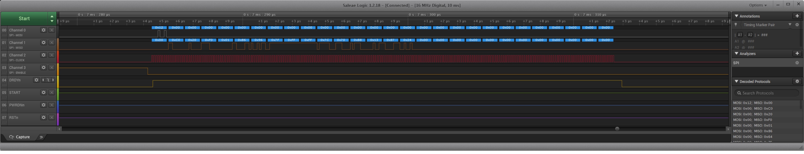
Most specifically and worringly, the ID register reads 0xC0 indicating it's only a 4-ch device and not an 8-ch, but the part is clearly marked ADS131E08S.
More distressingly, when I try and read data, I get 0x00 back for the read slots for Ch's 5-8.
This is the second device I used, the first device read back as 0x00 for CHnSet{5:8]. I thought perhaps I had written a bad device somewhere in my development. Now I'm beginning to question these devices, or am I just missing some step in the initialization?
Device ID: 0xc0 Config 1 : 0x94 Config 2 : 0xe0 Config 3 : 0xe1 fault : 0x00 ch1 set : 0x10 ch2 set : 0x10 ch3 set : 0x10 ch4 set : 0x10 ch5 set : 0x10 ch6 set : 0x10 ch7 set : 0x10 ch8 set : 0x10 flt statP: 0x00 flt statN: 0x0f gpio : 0x0f
Here is the register reading from my second device:
Device ID: 0xc0 Config 1 : 0x00 Config 2 : 0x00 Config 3 : 0xc9 fault : 0x00 ch1 set : 0x10 ch2 set : 0x10 ch3 set : 0x10 ch4 set : 0x10 ch5 set : 0x00 ch6 set : 0x00 ch7 set : 0x00 ch8 set : 0x00 flt statP: 0x00 flt statN: 0x0f gpio : 0x00
UPDATE: I've just noticed that I do in fact have ADS131E08S devices, and not the ADS131E08's I thought I ordered (from the TI store). However, I still only apparently have 4 channel devices instead of 8 channel devices, and therefore the registers still don't match!
Yes, I am following that procedure and meet the timings required.
Yes, DRDY is toggling both before and after I write the configuration registers, and START works as advertised.
And in reading the data sheet it mentions the first read might not be settled data. I read all the registers a couple of times just to be sure.
I am indeed getting what looks like fairly appropriate data on the first 4 channels, but all 0 on channels 5-8 - so it looks to me like I've got a 4 channel part that is marked as 8 channel?
I have attached the schematic for your reference. Also is a screen shot of my logic analyzer showing that the part does indeed stop sending data.