This thread has been locked.

If you have a related question, please click the "Ask a related question" button in the top right corner. The newly created question will be automatically linked to this question.

ADS1292R: Configure ADS1292R for EMG acquisition

Part Number: ADS1292R
Other Parts Discussed in Thread: ADS1298, ADS1292

Hi

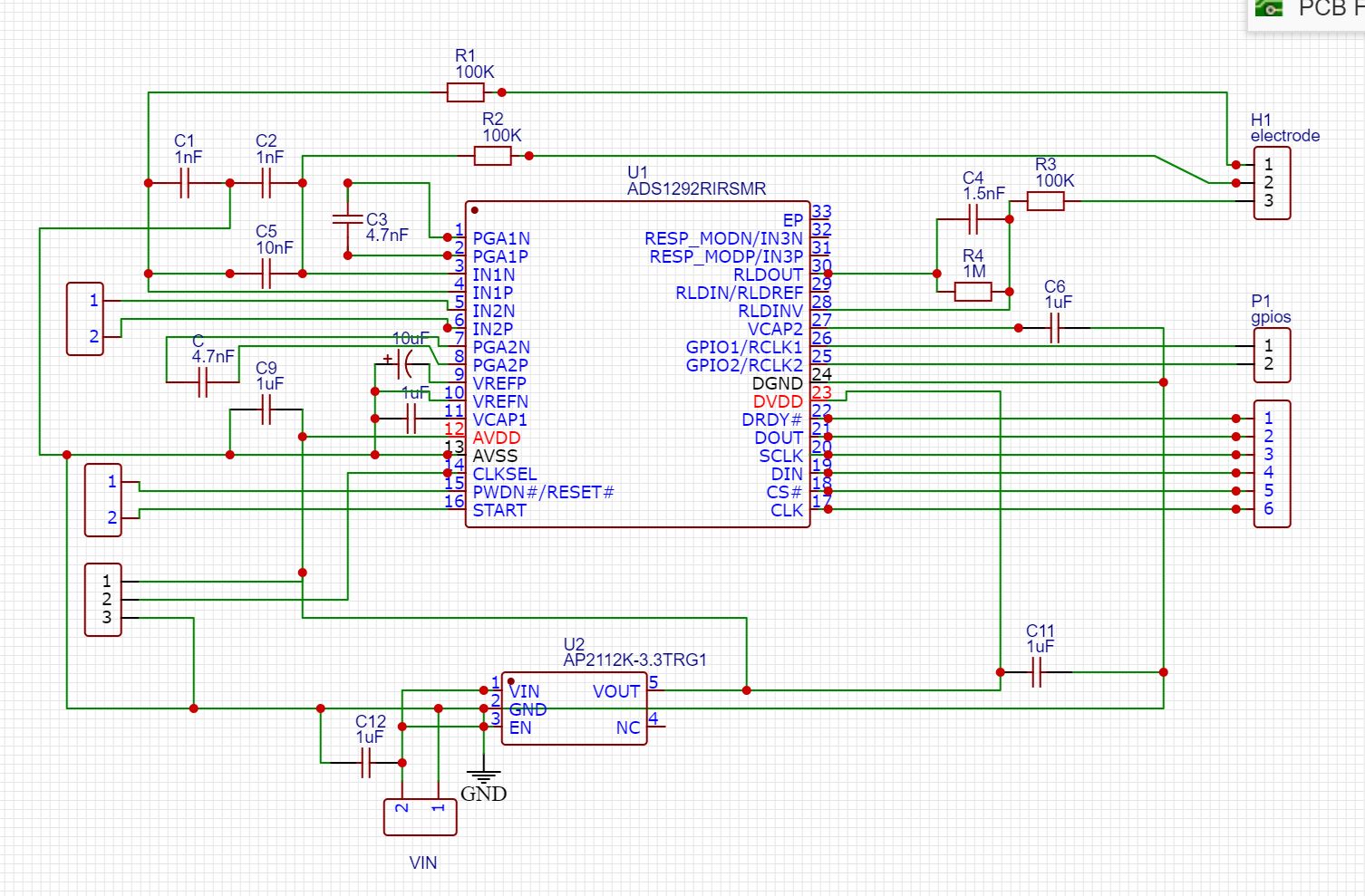
Thanks to the great support from this forum especially Mr Alexander Smith, Mr Ryan Andrews, Mr Tom Hendrick and Mr Collin Wells, the program is now converting the output codes back to EMG voltage successfully. Now, since the software part is almost complete, I am planning to optimise the hardware part. The schematic of ADS1292R to acquire EMG signals is shown below.

The following are the important points:

1. 3.3 V for both digital and analogue supply

2. RLD input for the reference potential

I have a few thoughts that require some clarifications

1. I have read that RLD can be sourced from the inputs (int this schematics 1N and 1P) and the circuit is as shown below:

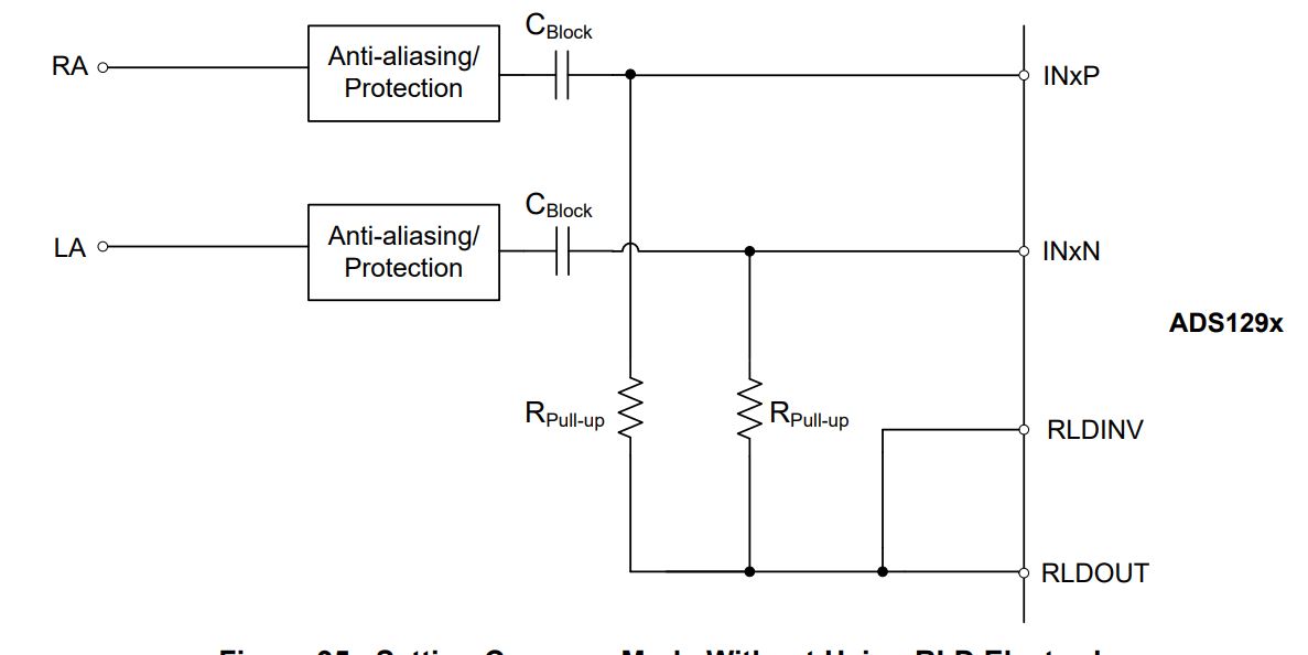
This seems a better approach. So using a capacitor and a pull-up resistor I can provide body reference to the IC. This is adapted from the ADS1298 datasheet. Can this be applied to ADS1292R?

2. If it is possible, what is the theory behind it? (in short, could anyone explain to me why this works?)

3. To convert the output codes to voltages, I use an internal reference (2.42 V). Does adopting this RLD configuration affect the reference voltage? ( I think the reference Vref is for ADC and RLD is for the amplifiers)

  • Thank you Harikshore!  Please don't forget Mr. Ryan Andrews!  He was a part of this as well.

  • Hi

    My apologies for not mentioning Mr Ryan Andrews. I have edited the post. He certainly has provided valuable information on this topic.

    Regarding the hardware parts, I am looking forward to hearing your thoughts. Thank you

  • Hi Harikishore,

    Happy to help! Thanks for the mentions! 

    This can be applied to ADS1292R. The point of this is to ensure that the measurement is within the common-mode range of the PGA, as well as counter some of the noise in the measurement.

    The input signals will have the signal of interest as well as some noise. The RLD amplifier derives a reference signal from the inputs, inverts it, then re-introduces the inverted noise to the measurement, cancelling out some of the noise. Since this inverted noise signal is present on both inputs, it is very efficiently cancelled out by the common-mode rejection ratio of the PGA. 

    Reference voltage is independent, either way it should still be 2.4V. 

    This post may help in terms of schematic design and the different options available to you: https://e2e.ti.com/support/data-converters/f/73/t/799662

  • Dear Mr. Alex,

    Thank you for your help!

    Currently, I use the RLD electrode for my design. The circuit is shown below (figure 1). And I use the following register settings:

    RLD_SENS: 00100000

    RESP2: 00000010

    By doing this RLD is powered On, RLD reference signal is generated internally and RLD not derived from any of the inputs.

    1. However, if I connect the RLD as mentioned in the original post (shown in figure 2), what changes shall I make to the RLD_SENS and RESP2 register settings? 

    2. What are the drawbacks of this method? Or does it have any other advantage over using the RLD electrode?

    3. Importantly, if I adopt this configuration, will this be effective when I use both input channels for EMG measurement? (Currently, I am using only one channel)

    4. Do I have to edit CH1SET register bits [3:0] to 0010 (RLD_MEASURE)?

    5. If I adopt this configuration, can I still use that channel for normal electrode input? Thus, I have a bipolar electrode configuration (2 electrodes) without a RLD electrode.

    So, I can still use the internal reference of 2.42 V by writing register CONFIG2.

    figure 1

  • Hi Harikishore,

    Ultimately, the RLD configuration depends on many factors. Such as what else is happening in the system, the environment, the level of accuracy that the design is trying to reach. More often than not, extensive debug is necessary in order to fine tune all of the different registers and get it working correctly. Using a dedicated RLD electrode is the preferred method, but it is not necessary and some designs prefer having a fewer number of electrodes. 

    1. You may want to use one or more of the channel inputs to derive the RLD signal in RLD_SENS. If you want to use a different reference, you could change that as well, but using mid-supply is fine for RESP2. 

    2. The draw-back is that the control loop is smaller. Less noise sources are accounted for, and it may not be as effective. 

    3. I see no issue.

    4. No. This is simply if you want to measure the RLD signal (which is a good thing to do when debugging RLD drive effectiveness) 

    5. Yes


  • Thank you Alex, I appreciate the detailed answer. Thank you.

    When I studied the datasheets of ADS1292 and the evaluation board, I found that in certain circuits (see the figure 1 as an example) two capacitors are connected in parallel with a significant difference in capacitance value. Hence, I designed the schematics (also shown in figure 2) by removing the smaller capacitor as the bigger one allows for some tolerance. Is it the right approach? Or the two parallel capacitors have any purpose? (eliminating the capacitor helps in miniaturization). 

    Figure 1:

    Figure 1

    Figure 2

    Figure 2The smaller capacitors are removed.