Other Parts Discussed in Thread: DLPC120-Q1, , DLP3030PGUQ1EVM
Hello Team,
Could you please help to share DLPC120-Q1 programming guide?
Thanks,
Sundar
This thread has been locked.
If you have a related question, please click the "Ask a related question" button in the top right corner. The newly created question will be automatically linked to this question.
Hello Team,
Could you please help to share DLPC120-Q1 programming guide?
Thanks,
Sundar
Hi Sundar,
Please see the attached documents.
DLPU061_Piccolo_SW_Guide_March2018.pdf
DLPU059_ACP_UsersGuide_March2018.pdf
Hope these help.
Thanks,
Alex Chan
Hello Alex,
Thanks for the response.
Could you please help to share DLP3030-Q1PGU Schematics with us?
Thanks,
Sundar
Hi Sundar,
Please see the following attachments.
The first one is for the formatter board.
2514132E_dlpc120_formatter.pdf
The second one is for the DMD interface board.
Thanks,
Alex Chan
Hello Alex,
Could you please help to share the document list attached in the image?
Thanks,
Sundar
Hi Sundar,
Please see the following attachments.
DLPU057_Piccolo_SPI_Command_Guide_March2018.pdf
DLP3030-Q1_full_datasheet_dlps076a.pdf
3681.dlpu055_DLPC120-Q1_I2C_User_Interface_Programmers_Guide_201803.pdf
I also believe I have already given you the controller and DMD board schematic files in a previous messages.
Thanks,
Alex Chan
Hello Alex,
Thanks for the documents.
We have a basic question.
Our understanding is we use SPI to control the brightness of DLP3030 as mentioned below.
PC/SoC-> SPI/USB to SPI->DLP3030 . Is our understanding correct?
Thanks,
Sundar
Hi Sundar,
Here is a quick overview of the connections. The connection between the PC and the EVM include 3 parts.
a.) USB B to USB A cable that goes from PC to Cheetah SPI Box
b.) Cheetah SPI Box which has a USB A port and ribbon cable female pins
c.) Cheetah to SPI cable #7 which connects the Cheetah Box to the Formatter board connector.
You can use the control program under System Control under Dimming Control you can adjust the backlight value to change the brightness.
Thanks,
Alex Chan
Hey alex,
Thanks for your reply
Kindly share me the BOM if its possible.
Thanks
Sundar
Hi Sundar,
Please see the following attachments.
The first excel sheet is the bom for the formatter board.
2514134E_dlpc120_formatter_BOM (1).xlsx
The second excel sheet is the bom for the dmd interface board.
Thanks,
Alex Chan
Hi alex,
Will you share the details for RGB LED and photodiode which is used in this DLP3030Q1EVM. If its possible kindly share the design files.
Thanks,
Saravanakumar D
Hi Saravanakumar,
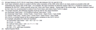
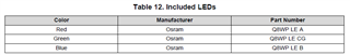
The RGB leds are Osram Q8WP LEDs and photodiode should be TEMD5020.
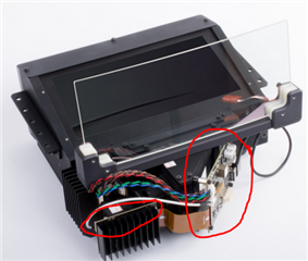
Unfortunately the design of the optical engine and LED board, which contains the LEDs and photodiode, was designed and created by a separate company and not TI so we do not have access to the design files.
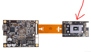
In the below image, TI only designed the DMD interface board and the formatter board which I have provided the links of the design files to in a previous message.
Thanks,
Alex Chan
Hello Alex,
Thanks for the response.
Could you please help to provide the optical parameter specification for "
Hello Alex,
https://software-dl.ti.com/secure/software/dlp_auto/HUD-DOC/dlpu065_CHUD_EVM_Users_Guide_201711.pdf?__gda__=1648840555_016044ddd667bfa33b0afb0b521ed2ed
Could you please help to provide access to this link? It shows Access Denied for us.
Thanks,
Sundar
Hello Sundar -
I can answer while Alexander Chan is out of office.
For the DLP3030PGUQ1EVM key optical specifications, please refer to Section 1.3 of the User's Guide.
For the CHUD EVM, this product is being discontinued. Can you remind me what information exactly you are looking for?
Regards,
Ross
Hello Ross,
Thanks for the response.
We need the information as similar to DLP5530 document which is attached in this for DLP3030 as below
Please help to provide those information
/resized-image/__size/320x240/__key/communityserver-discussions-components-files/94/DLP3030_2D00_InfoRequired2.png
Thanks,
Sundar
Hello Alex,
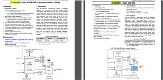
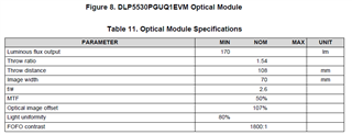
Sorry, I Need Optical Parameter details of DLP3030, For that, I sent DLP5530 Optical Parameters as a reference in the 3 images. We need similar information for DLP3030.
Please help to share the Optical Parameter Details of DLP3030.
Thanks,
Sundar
Hi Sundar,
My apologies for misreading the question.
We provide the specifications in the user guides for the DLP3030CHUDQ1EVM which can be found here:
https://www.ti.com/lit/pdf/dlpu065
For specifications for the DLP3030PGUQ1EVM you can find the user guide here:
https://www.ti.com/lit/pdf/dlpu064
Thanks,
Alex Chan
Hello Alex,
Thanks for the quick response.
Could you please help to share the part numbers of RED, GREEN, BLUE LED?
Also please help to share the electrical specification of DLP3030?(This information is not available in the above documents)
Thanks,
Sundar
Hi Sundar,
The LED used is the OSRAM Q8WP RGB LEDs.
Some of the electrical specifications are already in the user guides the only thing I would add is the drive current for the OSRAM Q8WP is 6A.
Thanks,
Alex Chan
Hi,
I believe the scheme would be feasible I will need to double check but the overall block diagrams are identical between the DLP3030 DMD and the DLP3020 DMD. I do not believe we have a current solution on the market utilizing the DLP3020AFQRQ1 DMD.
What you may need to design is a new dmd interface board compared to what is currently offered on the DLPC3030Q1EVM (https://www.ti.com/tool/DLP3030Q1EVM?keyMatch=DLP3030Q1EVM). I have attached the schematic design of the dmd board as well which you can use as a reference.
Additionally may I ask your name and what company you are with and if you have any other questions please feel free to reach out.
Thanks,
Alex Chan
Helllo,Alex Chan
Yes, I have realized that making HUD with dlp3030q1evm circuit board and dlp3020afqrq1 requires designing an interface circuit. So what problems should we pay attention to when designing interface circuit?
My surname is Wang. You can call me Mr. Wang. I work in a company that produces optical and electronic related products.
Thanks,
Mr.Wang
Hi,Alex Chan
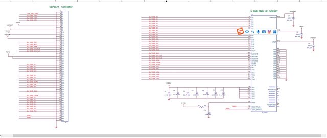
We have an interface design scheme for DLP3021 DMD, which is the following design.This design includes two kinds of circuit boards. Can this design be applied to DLP3020 DMD? The schematic diagram is as follows:
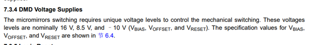
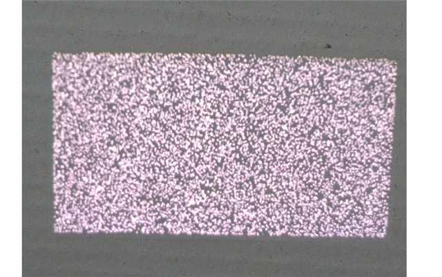
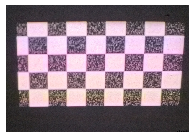
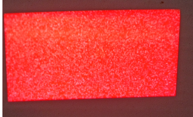
In addition, the scheme we made can be displayed normally before. But then there were some problems. 16V, 8.5V and - 10V voltages also existed, but they could not be displayed normally (there was interference like snowflakes in the display effect). What was the reason? Can you give me some advice?The display effect is as follows:
Thanks,
Mr.Wang
Hi Mr.Wang,
I am looking into the schematic you had sent and will need some time to look it over. Thank you for your patience.
Have you ensured the DMD is securely connected to the interface of the dmd board. Snowflakes like what you are showing typically mean the DMD isn't properly connected to the socket/PCB.
Thanks,
Alex Chan
Hi Mr. Wang,
I am closing this thread because of this new question that has formed that is different from the initial question. Please start a new thread if you have any other questions.
Thanks,
Alex Chan
Hello Alex,
Could you please help to provide access to download DLPC120
DLP Auto HUD Gen 1.5 - DLPC120 Automotive Control Program (Object)
Thanks,
Sundar
Hi Sundar,
You can find the DLPC120 Automotive Control Program Lite here.
https://www.ti.com/tool/DLP3030Q1EVM?keyMatch=DLP3030Q1EVM
Thanks,
Alex Chan
Hello Alex,
This is lite version. I need full version of DLPC120 Automotive Control Program.
Please help to share.
Thanks,
Sundar
Hi Sundar,
Sorry did not realize you needed the full version.
What is a good email I can use to send you the full version of the DLPC120 Automotive Control Program.
Thanks,
Alex Chan
Hi Sundar,
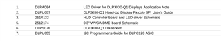
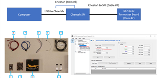
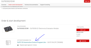
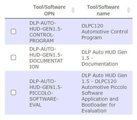
I have granted access to the following please let me know if you can successfully access these items and get access to download the Gen 1.5 Control Program.
The 1.5 documentation folder should have user guides on the DLPC120 Automotive Control Program and other useful documents.
Thanks,
Alex Chan
Hello Alex,
Thanks for the link and we were able to download.
Could you please help to share the display timing parameters of DLP3030? I have searched in documents but not able to find it.
Please help us on this.
Thanks,
Sundar
Hi Sundar,
Please see the following DLPC120-Q1 datasheet specifically sections 6.9 and 6.10.
Thanks,
Alex Chan
Hello Alex,
Thanks for the reply.
Please go through this question and its raised by myself.
We have an issue with the setup as mentioned in the above question link.
Could you please help to clarify if we get 800x800 input to DLP will it crop to 800x480? Do you think TCON will do cropping of 800x800 to 800x480 and will work along with DLP 3030?
TCON with DLP3030 is possible? If yes please help to suggest TCON part number.
Thanks,
Sundar
Hi Sundar,
Sorry I am not sure what TCON is and the DLP 3030 will only support whatever video resolutions are listed in the datasheet.
Thanks,
Alex Chan
Hello Alex,
Regarding DLPC120 firmware programming, Is there any way to read the existing firmware from the EVM board using DLPC120 control program?
Thanks,
Sundar
Hi Sundar,
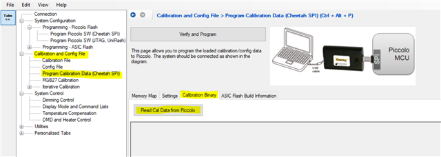
The DLPC120 does not support many options for reading the existing firmware from the EVM board. You are able to read some information like the calibration data but it is in binary format and is not readable.
Is there something specific you are trying to learn or access from the firmware for the EVM.
Thanks,
Alex Chan
Hello Alex,
We are planning to design our own DLP3030 , for that we need to have provision to read and write the firmware on DLPC controller.
As of now write permission is there we can see.
Suppose if we need to read the exisiting firmware means how to do that? Please suggest.
Also , I believe we have only one firmware for DLPC controller and other components seperate firmware not required. Please clarify.
Thanks,
Sundar
Hi Sundar,
Is this other e2e ticket what you may be interested in.
There is a user guide with useful SPI commands that can provide all the necessary interfacing and communication.
Thanks,
Alex Chan
Hello Alex,
Thanks for the link, we will go through it.
Could you please help to suggest what is the minimum and maximum horizontal and vertical blanking period supported by DLPC120?
Because in the below question
https://e2e.ti.com/support/interface-group/interface/f/interface-forum/1112450/ds90ub941as-q1-symmetric-asymmetric-splitting-of-ds90ub941/4126334#4126334
the vertical blanking period is coming around 800-480=320, will DLP3030 accept that much vertical blanking period? Please help to clarify.
Thanks,
Sundar
Hi Sundar,
I am going to have to look into this further sorry for the delay and thank you for your patience.
Thanks,
Alex Chan
Hi Sundar -
The best way to determine if the DLPC120 can handle specific blanking periods is to simply test it with a physical setup. Do you have an existing setup?
The Parallel Interface Supported Resolutions table from the DLPC120-Q1 datasheet only provides typical timing, as this is all that we've tested. You may be able to provide input at timings that do not match the typical values inside this table, but we recommend testing it. Also, please refer to Note 3 from this table:
Regards,
Ross