This thread has been locked.

If you have a related question, please click the "Ask a related question" button in the top right corner. The newly created question will be automatically linked to this question.

DLP5531Q1EVM: System is busy

Part Number: DLP5531Q1EVM

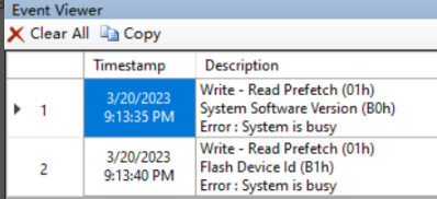
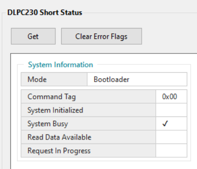
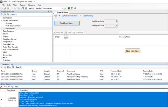
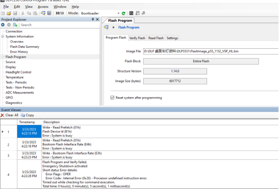
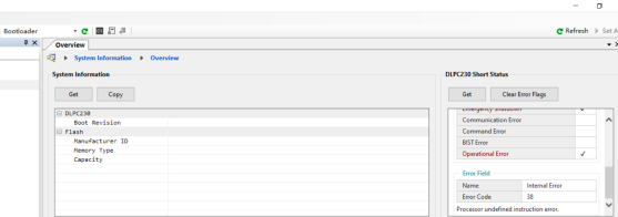
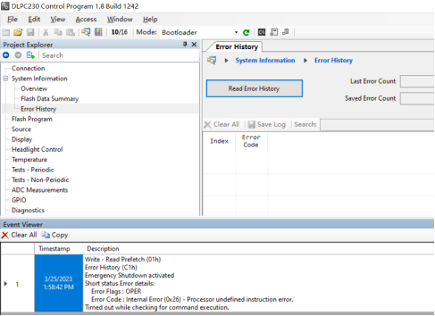
We bought a DLP5531Q1EVM from TI and made a new EVM modeled after its circuitry. When connecting with the modified EVM using the DLP control program software, it tells us that the evm is in BOOTLOADER mode with SW3 ON. Then I want to get the system information, which tells me the system is busy.

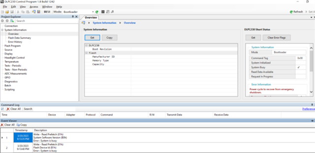
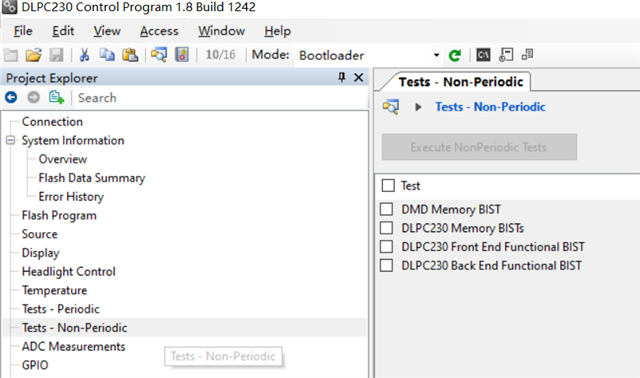
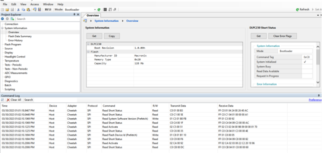
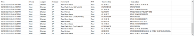
The modified board system is busy(in Bootloader mode).

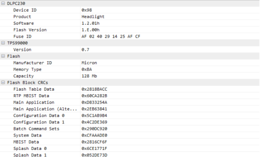
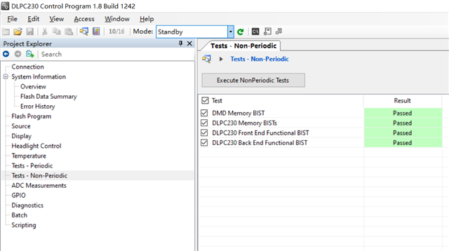
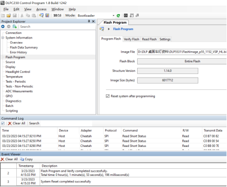
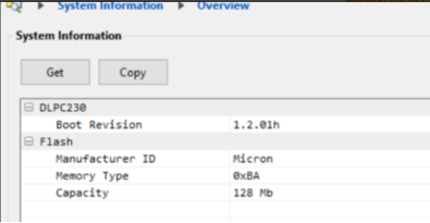
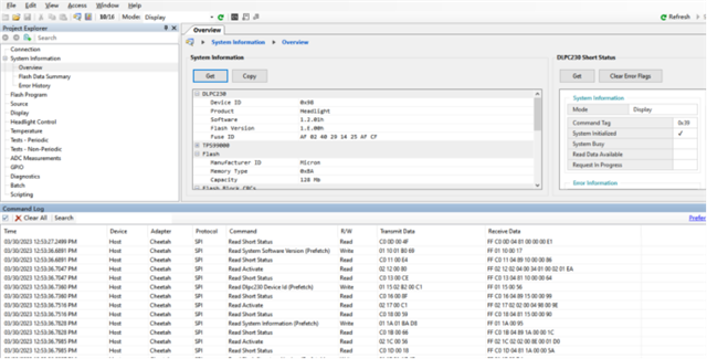
Normal system information obtained from TI board(in Display mode).

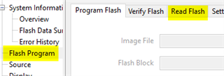
I set SW3 OFF to get system information and also download FLASH to EVM.
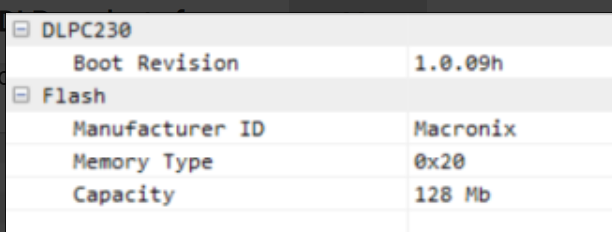
After comparison, I found that the system information obtained from the EVM modified in Bootloader mode was somewhat different from the information obtained from the EVM purchased from TI.

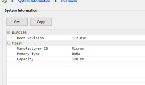
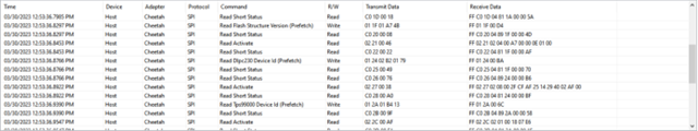
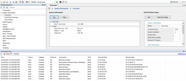
 the system Information in Bootloader mode(purchased from TI)

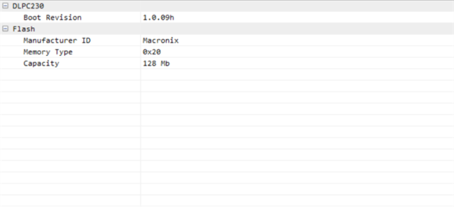
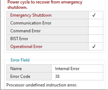
Modified EVM system information in Bootloader mode

1. What causes the system to be busy when the DLP control program reports an error?
2. Why can't my EVM SW3 enter the main application in any position?
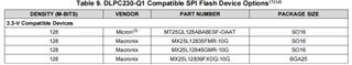
3. Why is DLP230 Boot Revision and FLASH Memory Type different from EVM purchased from TI?

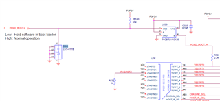
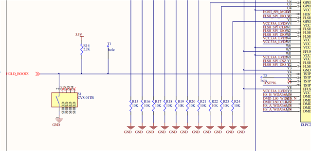
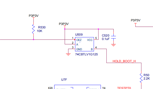
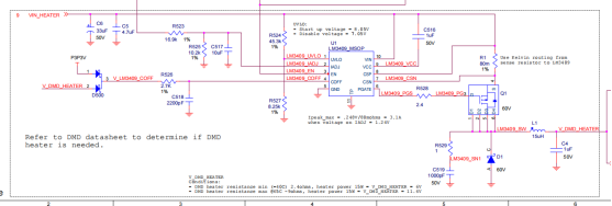
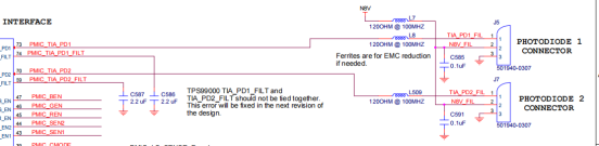
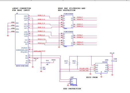
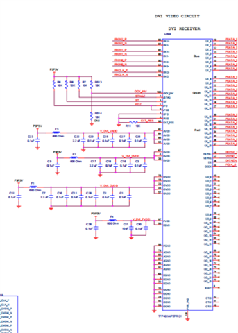
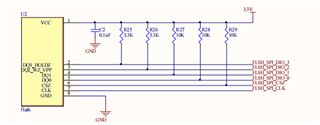
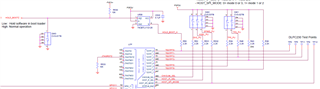
This is our schematic diagram of the circuit.

DLP.pdf

  • Hello Cherry,

    Thank you for the detailed information.  One of our team will respond to this after looking at what you provided.

    Fizix

  • Hi Cherry,

    We actually need a couple of days to check into this in more detail.  

    Are you able to read the non-periodic diagnostics and see if there are any errors reported?  

  • Ok, thank you.

  • It seems like you can only read the non-periodic diagnostics BY going into STAND BY MODE, but I can't go into STAND BY MODE and be in Bootloader MODE all the time.

    Evms purchased from TI read normally.

    The modified board is in Bootloader MODE and cannot be read.

  • Hi Cherry, 

    It seems like there maybe a HW issue.  The DLPC230 will stay in boot mode if TESTPT0 (pin Y4 of the DLPC230) is high.  Can you measure pin Y4 or the bottom side of R50 to make that the modified board is driving this pin to "0" or low?    Does the modified board have this exact same circuit as below?

    Please see the two images below from the EVM schematic and DLPC230 datasheet.

    Thanks,
    jason

  • Hi Jason,

     The board is still in Bootloader Mode, regardless of whether I make the modified board push the pin Y4 to "0" or "1". My circuit removed the U509 switch because I thought one switch was sufficient to control the high and low signal of this pin. Could that be the reason?


    The modified board


    TI EVM 

    Thanks,

    Cherry

  • Hi Cherry -

    The "Error History" page can the most helpful, as it typically displays a list of all encountered error codes. Usually this helps us to find the root cause of these kind of issues. Can you please share a screenshot of this page?

    Thanks,

    Ross

  • Cherry, sounds like the HW is not the issue.  

    See message from Ross to capture the error history.  Also, the next major area that could be a possibility is to verify that the SPI flash is programmed and programmed correctly.  If the DLPC230 gets errors reading data from the flash, then it will stay in boot.

    jason

  • Hi Ross,

    The "Error History" page tells me my device was activated with an emergency shutdown.


    Thanks,

    Cherry

  • Hi Jason,

    I made the DLP230 of the modified board push Y4 to "1".At this time I was able to download FLASH successfully.

    But when I pushed Y4 to "0", I couldn't do anything with FLASH and started reporting system busy.The emergency shutdown was also opened.

    Thanks,

    Cherry

  • Hi Cherry - thank you for providing this information. The team is digging into the details of the software to try to understand what may cause this issue. I also have a few more questions:

    1) Can you explain the differences of your board compared to the TI EVM?

    2) What version of DLPC230 flash have you programmed onto your EVM?

    Thanks,

    Ross

  • Hi Ross,

    We modified the board to remove the DMD heater, HDMI interface and related circuits, photodiode interface and related circuits.

    All the circuits above have been removed.I downloaded this FLASH. My flash chip uses MX25L12833F, does it matter?

    Thanks,

    Cherry

  • Hi Cherry,

    Ross is out today.  I want him to comment on the removal of the circuits.  It seems like it should be OK, but I want him to review it on Monday.

    The boot error 0x26 seems to indicate that the system immediately goes to a unrecoverable error.  It seems like either the flash part is not compatible or the data is somehow corrupt.


    For the flash device, which version did you use.  Did you use the MX25L12833FMR-10G?  We think this one should work, but not sure about the other versions.

    Thanks,

    Jason

  • Hi Jason,.

    Could there be any other reason for an error like 0x26 on my system? My FLASH chip is mx25l12833fm2i-10g. According to what you mean, the chip should be fine.

    I got an error 0X26 while reading the error history.

    I got an error 0X38 while reading the system information.

    TI EVM Boot Revision

    MY EVM Boot Revision

    Is Boot Revision the reason why EVM is in BOOT? How did this BOOT Revision change?


    Thanks,

    Cherry

  • Hi Cherry -

    The removal of those particular circuits should not be a problem. 

    Regarding the Flash version: , where did you download this file from?

    One recommendation I have is to use the "Read Flash" feature of the ACP to save the flash version from the TI EVM, and then re-program that version onto your version of the EVM. 

    Are you able to do so?

    Regarding the Boot Revision number, our team is still investigating what could cause this difference.

    Regards,

    Ross

  • Hi Ross,

    I downloaded my FLASH version from the security source your techies gave me.

    I used ACP's "read Flash" function to save the Flash version in TI EVM, and then reprogrammed that version into my EVM version. But then it didn't seem to work. I didn't know if it was a flash download problem.

    I made the DLP230 of the modified board push Y4 to "1".At this time I was able to download FLASH successfully.But When I set Y4 to "0" and tried to verify the flash version, the DLP 230 CONTROL PROGRAM started reporting errors.

    Thanks,

    Cherry

  • Hi Cherry,  

    Sorry, but we do not immediately have an idea on the cause of this issue.  We are going to spend more time to investigate the boot loader difference and brainstorm some other possibilities.

    In general, it seems related to the flash or binary file because the system immediately goes to standby mode.

    Let us discuss more and come back tomorrow.

    Thanks,

    Jason

  • Hi Jason,

    I'm looking forward to your reply.

    Thanks,

    Cherry

  • Hi Cherry,

    The official boot rom release version is 1.0.09, There are no other versions as it is fixed in HW. The boot revision returns the version obtained from the Read System Software Version command.  Can you please double check the return values? Specifically, which system is returning what version?

    Please share the command logs for both systems (TI EVM and your new system) when doing a Get in the System info page to have confirmation. Please clear the command log first then read back the system info and share a screenshot of that log output.  We just want to double check the boot rom version, as this should never change.

    Here are the error codes below:

    Error Code

    Description

    26 (0x1A)

    Invalid flash device

    38 (0x26)

    Undefined instruction abort

    56 (0x38)

    FDMA SW Abort Error

    We are still not quite sure what is causing this issue, but still the most likely cause is something with the flash device.

    One experiment that you might consider is to move the flash device from the TI EVM to your new board.    Or, move the new flash device to the TI board to see if you have the same problem.  This would at least rule out the PCB design if the problem follows the flash device.

    Thanks,

    Jason

  • Hi Jason,

    Now is the situation of our modified EVM.

    So here's the TI EVM situation(DISPLAY).

    TI EVM situation(BOOT)

    I'll see what happened with the flash drive and then I'll talk to you again.

    Thanks,

    Cherry

  • HI Cherry,

    Thanks for trying the flash drive test.  We will keep checking other ideas based on this information.

    Thanks,

    Jason

  • Hi Cherry -

    Just checking in. Please let us know if there is anything else TI can do to help with this issue? If not, then we will close this thread.

    Thank you!

    Ross 

  • Hi, Jason,

    The board we modified used FLASH encapsulated in SOP8, but your official website recommended FLASH of SOP16. Could that be the reason?

    Thanks,Cherry

  • Hello Cherry,

    Thank you for your question, we're looking into the issue and will get back to you within the next few days. We appreciate your patience.

    Best,

    Maxine

  • Hi Cherry,

    Sorry for the delay.  Can you please send your flash connections between the DLPC230 and flash device?  Here is the schematic for the TI reference:

    Yes, there could be something about the 8-pin device that is different.  We have not tested this device in TI, so it is difficult to know for sure.

    We will keep checking, but please send your schematic of the flash area.

    Is it possible that there is some difference in the mode of operation supported by the 8 pin device?  See the required modes from the DLPC230 datasheet.


    Thanks,

    Jason

  • Hi Cherry,  were you able to resolve the issue?   Can you send the 8-pin schematic of the flash interface for us to review?   We do not have any more ideas at this point.  We will wait for your next update.

  • Hi Jason,

       We tried your recommended flash device MT25QL128ABA8ESF-OAAT. But it's still in BOOTLOADER mode.


    Then the system reports the following error:


    I checked your programming manual. It tells me that errors 35-58 in BOOT mode are internal errors and need to contact TI. I would like to know what situation caused internal error 38.


    In addition, I want to erase my flash content by Scripting function in DLPC230 Control Program software. How do you do that? Or is there another way to erase FLASH content?

    Thanks,

    Cherry

  • Hi Cherry -

    I checked our internal documentation for error codes, and here is the description for Bootloader Error Code 38: "Processor experienced an unrecoverable instruction prefetch exception."

    Unfortunately, this error code does not provide a direct indication of the root cause.

    Given that you've now tried two different flash parts, both which should be compatible with the DLPC230, our suspicion is related to the hardware. Can you please send the 8-pin schematic of the flash interface for us to review?

    Regards,

    Ross

  • Hi Jason,

       We tried your recommended flash device MT25QL128ABA8ESF-OAAT. This FLASH has 16 interfaces.But it's still in BOOTLOADER mode.

    This is a schematic of our 8 interface FLASH.

    This is a schematic of our entire board.

     7043.DLP.pdf

    Thanks,

    Cherry

  • Hi Cherry - thank you for sharing. Let us review with our HW team and get back to you.

    Regards,

    Ross

  • Hi Ross,

      I'm looking forward to your reply.


    Thanks,

    Cherry

  • Hi Cherry - we will reply tomorrow.

    Regards,

    Ross

  • Hi Cherry - 

    The schematics look okay. Have you done a continuity test on this DLPC230-flash interface in order to verify that the signals are routed correctly on the PCB layout?

    Also, did you verify that you have the correct switch configurations for these signals? You can compare them with the TI EVM to understand the proper configuration. The key ones to consider are the STAY-IN-BOOT, EXT-BOOT-EN, and ALT-MADR-SEL.

    Regards,

    Ross

  • Hi Ross,

    I compared my board to the test pins of the TI board. The STAY-IN-BOOT and EXT-BOOT-EN on our board are the same as on the TI board. The STAY-IN-BOOT signal is low, and the EXT-BOOT-EN signal is low. The ALT-MADR-SEL on our board is different from the TI. The ALT-MADR-SEL signal is low on the TI board and high on our board. Why does this happen? Can the ALT-MADR-SEL signal be changed?

    Thanks,

    Cherry

  • Hi Cherry - we are investigating this possibility and will get back to you.

    Thanks,

    Ross