DLP Lightcrafter™ 4500
Frequently asked questions on the DLP Lightcrafter™ 4500 evaluation module (EVM).
1. Optical Properties of the DLP Lightcrafter™ 4500 EVM
2. What is the latency caused by loading patterns from the flash memory?
Depending on your application, you may have more than 48 bit planes in your sequence, in which case the DLP Lightcrafter™ 4500 will have to load from the flash memory. How long this memory load takes depends on the type of images being loaded from memory. It is important to design your system such that it is slow enough to account for the worst case load time. The DLPC350 takes a worse case time of 200ms to load images from the buffer. Loading the buffer from flash takes an amount which depends on the image complexity. Please refer to the following threads for some additional information:
https://e2e.ti.com/support/dlp__mems_micro-electro-mechanical_systems/f/924/t/459126
https://e2e.ti.com/support/dlp__mems_micro-electro-mechanical_systems/f/924/t/371324
https://e2e.ti.com/support/dlp__mems_micro-electro-mechanical_systems/f/924/t/381585
3. How do the different triggering modes work on the DLP Lightcrafter™ 4500?
The DLP Lightcrafter™ 4500 has several different triggering modes available for use. The basics are covered in the user's guide for the DLP Lightcrafter™ 4500 and in the programmer's guide for the DLPC350 (page 41). In the future we'll be adding a walked through example utilizing one of these trigger modes. Stay tuned!
4. I want to write my own software to interface with the DLP Lightcrafter™ 4500 or DLPC350.
Sometimes it is necessary to create your own software to interface with the DLP Lightcrafter™ 4500 or DLPC350. To accomplish this goal, Texas Instruments recommends doing the following:
-Consult the programmer's guide for the DLPC350 to get familiar with how to program it: www.ti.com/lit/ug/dlpu010e/dlpu010e
-Download the source code for the DLP Lightcrafter™ 4500 GUI found here: http://www.ti.com/tool/dlplcr4500evm
-Download the DLP® ALC SDK: http://www.ti.com/tool/dlp-alc-lightcrafter-sdk
With these tools, you'll be able to get an understanding what commands the DLPC350 expects to see for certain operations and begin building your own control software from there! You can peek inside the source code for both the SDK and the GUI, giving you a detailed understanding of what's going on behind the scenes.
5. USB Connection is not recognized.
6. What is the difference between Pattern Display and Variable Exposure Pattern Display?
7. How fast can patterns can be displayed in pre-stored mode?
This information can be found in the DLP Lightcrafter™ 4500 user's guide. The table is reproduced below:
| Bit Depth | Preloaded Pattern Rate (Hz) |
| 1 | 4225 |
| 2 | 1428 |
| 3 | 636 |
| 4 | 588 |
| 5 | 500 |
| 6 | 400 |
| 7 | 222 |
| 8 | 120 |
8. How do I get my DLP Lightcrafter™ 4500 to display at 120Hz?
Perhaps you'd like to run your DLP Lightcrafter™ 4500 at 120Hz. To accomplish this, you'll need to reduce the blanking time on the GUI to successfully get 120Hz output. Keep in mind that in pattern sequence mode, you'll only be able to display an 8bit depth image at 120Hz. If you'd like to use the other 16 bits of the video frame data, consider breaking your video frame into smaller bit depth chunks. Please use the settings in the following image:
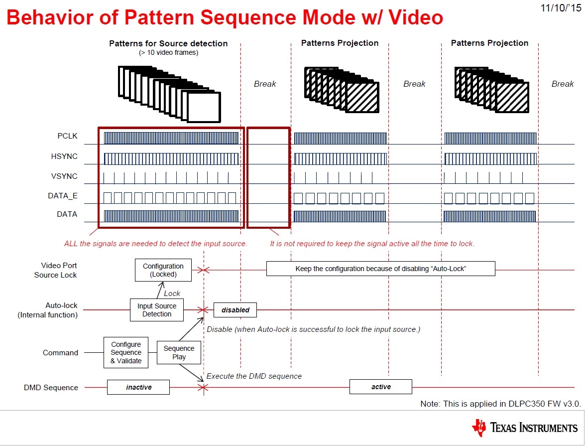
9. How does video source detection work in pattern display mode and RGB parallel video as the source?
If you'd like to use pattern sequence mode with video input data, please refer to the image below.
10. How is the video source detected and how can you use the information from AutoLock?
The video source is detected by the DLP Lightcrafter™ 4500 evaluation module and the status of this detection process is given by the input video signal detection status register. This register works for RGB parallel interface as well as FPD-link interface. The register is able to provide information on resolution, the controller's status in the signal detection process, clock signals, and more. Please consult the DLPC350 programmer's guide, section 2.1 for more information: www.ti.com/lit/pdf/dlpu010
11. How can I use an alternate flash device rather than the flash available on the Lightcrafter™ 4500 EVM board?
The Lightcrafter™ 4500 GUI v3.1.0 uses a local file to check the flash parameters that it needs to access. In the case where there is a custom board with a different flash device other than the default flash on the EVM, some modfications are needed. Please note no changes are needed if you are using the EVM flash device.
The local file containing the flash device parameters (FlashDeviceParameters.txt) can be found in the GUI installation folder on your system. This file contains the flash information that the GUI needs. The following information are provided in this file and need to be updated to your specific device:
- Mfg
- MfgID
- Device
- DeviceID
- Mb
- Alg
- Size
- Number of Sectors
- Sector Starting Addresses
Please make sure to follow the same format as in this file. After updating this information, the GUI will be able to access and update the mentioned flash device. Note that this option is available on GUI 3.1.0 and is not supported in previous versions.


