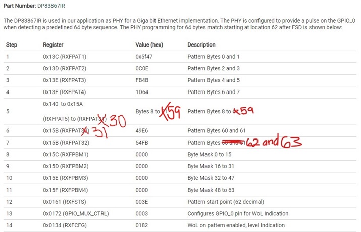
Part Number: DP83867IR
The DP83867IR is used in our application as PHY for a Giga bit Ethernet implementation. The PHY is configured to provide a pulse on the GPIO_0 when detecting a predefined 64 byte sequence. The PHY programming for 64 bytes match starting at location 62 after FSD is shown below:
|
Step |
Register |
Value (hex) |
Description |
|
1 |
0x13C (RXFPAT1) |
0x5f47 |
Pattern Bytes 0 and 1 |
|
2 |
0x13D (RXFPAT2) |
0C0E |
Pattern Bytes 2 and 3 |
|
3 |
0x13E (RXFPAT3) |
FB4B |
Pattern Bytes 4 and 5 |
|
4 |
0x13F (RXFPAT4) |
1D64 |
Pattern Bytes 6 and 7 |
|
5 |
0x140 to 0x15A (RXFPAT5) to (RXFPAT31) |
Bytes 8 to 61 |
Pattern Bytes 8 to 61 |
|
6 |
0x15B (RXFPAT32) |
49E6 |
Pattern Bytes 60 and 61 |
|
7 |
0x15B (RXFPAT32) |
54FB |
Pattern Bytes 60 and 61 |
|
8 |
0x15C (RXFPBM1) |
0000 |
Byte Mask 0 to 15 |
|
9 |
0x15D (RXFPBM2) |
0000 |
Byte Mask 16 to 31 |
|
10 |
0x15E (RXFPBM3) |
0000 |
Byte Mask 32 to 47 |
|
11 |
0x15F (RXFPBM4) |
0000 |
Byte Mask 48 to 63 |
|
12 |
0x0161 (RXFSTS) |
003E |
Pattern start point (62 decimal) |
|
13 |
0x0172 (GPIO_MUX_CTRL) |
0003 |
Configures GPIO_0 pin for WoL Indication |
|
14 |
0x0134 (RXFCFG) |
0182 |
WoL on pattern enabled, level Indication |
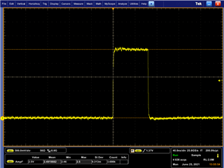
The setup worked fine when we sent the pattern and it provided the pulse at the GPIO_0 pin as expected. We also verified that if we do send a slightly corrupted pattern , the PHY does not recognize it by mistake. The problem that we are facing is that after about one hour of the PHY operation it generates false WoL detections without receiving the correct pattern. We checked the PHY registers after the false WoL detection but we found that their settings have not been corrupted. The same behavior was tested several times and with several hardware boards. Changing the starting position for the WoL pattern to 42 seems to solve the problem: after 48 hours no false WoL was received. Do you have an explanation for this strange behavior ? Is anything that we did wrong in the setup? Thank you