This thread has been locked.

If you have a related question, please click the "Ask a related question" button in the top right corner. The newly created question will be automatically linked to this question.

TCA9538: Circuit review required : TCA9538PWR & DRV8800PWPR

Part Number: TCA9538
Other Parts Discussed in Thread: DRV8800

Dear Sir/Ma'am,

We are using TI part, TCA9538PWR & DRV8800PWPR in our circuit as shown in below schematic snapshot (Image 1st & Image 2nd).

Please review this circuit design and let us know, for improvement. Also provide recommendation to overcome Noise/glitches.

 Image 1

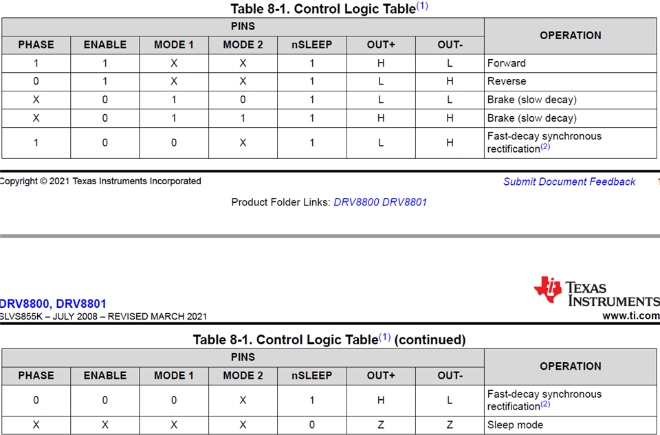
Image-1st= I/O Expander Circuitry

 Image 2

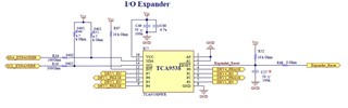
Image-2nd= Each Driver IC Circuitry (Total 4)


 Main highlights of the circuit are-

  • I2C signals of Expander IC TCA9538PWR, is connected to controller side with 4.7k pull up resistance connected to Vcc~3.3V
  • We are not going to use INT (interrupt) feature of the Expander IC, so we simply connected to Vcc with a pullup resistance of 10k.
  • RESET pin of the Expander IC is connected to Vcc with a pullup resistance of 10k.
  • A0 & A1 pins are connected to ground. ( for selecting I2C address of the device)
  • All 8 IO pins are connected to PHASE & ENABLE signals of four driver ICs DRV8800PWPR.
  • OUT+ & OUT- signals of each driver IC, are connected to coil of bi-stable switch/relay.
  • PHASE & ENABLE signals are controlled from the microcontroller by applying command to IO Expander IC over I2C signals, the driver IC will provide drive pulse (duration of 20 m sec) for the operation of switch coil.
  • No Freewheeling diodes used to protect the driver IC, as inbuilt protection.


When we implemented this prototype circuit & performed switch operations, we observed Noise on the pins of RESET & Vcc of Expander IC due to switch operation.

Due to this noise, IO Expander IC got RESET & configuration register got initializes.

To overcome this issue we are going to use bypass/decoupling capacitors on RESET & Vcc Pin of Expander IC. Please tell us regarding recommended value of these capacitors.

Please provide solution ASAP.


With Thanks & Regards,

Amit

  • Hi Amit,

    I am only going to comment on the I2C device. I am going to find out which team can review the schematic of the DVR8800.

    The schematic looks good overall.

    • The decoupling capacitors on VCC are well valued.
    • Make sure that the pull up resistors on SDA  and SCL are within the recommended resistance range.
    • Since you are not using INT you can just leave it floating. No need to connect any components to it.
    • It looks like all your port pins are outputs
      • Just in case some of them are inputs, make sure that all input pins are referenced to either VCC or GND with a resistor.

    When it comes to noise there are many ways to reduce it on a circuit. If your noise is coming in at a certain frequency you can look into filtering it out.

    Decoupling capacitors are great for reducing a ripple voltage. If you are using decoupling capacitors make sure:

    • they are placed as close to the pin as possible.
    • They are surface mount
    • They are ceramic capacitors with low ESR and ESL.

    The more expensive but most reliable way is to use an LDO linear regulator. These chips that are made to take a noisy power supply input and regulate to a defined voltage. Here is a list of linear regulator LDOs that TI makes.

    I am also going to add Bobby Nguyen to the thread to see if he has any ideas on how to minimize noise on this device.

    Best,

    Chris

  • Amit,

    We've notified a member of the DRV8800 team to review this schematic, thanks for your patience.

    Regards,

    Eric Hackett

  • Amit,

    Sorry for the delay here, we're still trying to contact someone from the DRV team to look at this. 

    Regards,

    Eric Hackett

  • Hello, Amit,

    For DRV8800, please separate nSLEEP and Enable pin.

    1. If they are connected together, it disables a lot of useful operation mode.

    2. nSLEEP from low to high may take some time to wake up the device. The output may not follow the ENABLE pin signal immediately. 

    Regards,

    Wang 

  • Hi Wang,

    Thanks for reviewing this circuit.

    Regarding DRV8800 IC, we have tied these signal (nSLEEP & ENABLE) to ensure power saving during normal mode. So that whenever we enable the IC, It also comes out from sleep mode. 

    Alternately you can suggest the maximum delay taken by the device to wakeup, so we can operate this circuit accordingly.

    Beside it, I need only confirmation that Interfacing of IO Expander IC TCA9538PWR & driver IC DRV8800PWPR will not create any Interfacing Issue or any failure in long run.

    Regards,

    Amit

  • Hi Chris,

    Thanks for reviewing this circuit.

    Regarding IO Expander IC TCA9538PWR, we have selected 4.7k pull up resistance value for SDA & SCL signals of I2C. We already referred

    slva689 application note of TI for this calculation. 

    Beside it, I need only confirmation that Interfacing of IO Expander IC TCA9538PWR & driver IC DRV8800PWPR will not create any Interfacing Issue or any failure in long run.

    Regards,

    Amit

  • Amit,

    Wang is out of the office now, but I see one question on DRV8800 above.  Plan for 1ms for "wake up" time from nSLEEP pin transitioning to high state. 

    Regards,

    Ryan

  • Hi Ryan,

    Thanks.

    I have one more query. Can you Please tell me that, in case if I am using only four port pins (P0 P1 P2 P3) of IO Expander IC, we will not use remaining four port pins (P4,P5,P6,P7).

    what things that should be taken care in hardware & firmware.

  • Hi Amit,

    If you are not using four of the port pins you can set them up as output pins. This way you will not have to worry about referencing them using a pull up/ down resistor and they won't generate interrupts.

    Best,

    Chris