This thread has been locked.

If you have a related question, please click the "Ask a related question" button in the top right corner. The newly created question will be automatically linked to this question.

DS90UB954-Q1: POC circuit

Part Number: DS90UB954-Q1

Hi Team,

We saw two POC circuit in datasheet. Here are two questions.

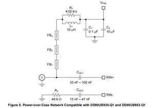
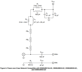
  • Why sometimes use 1*RL and sometimes 2*RL?
  • Customer need more specific to the requirements of component parameters, such as SRF requirements, inductor's S-parameters  in particular. Customer tested the 47uH inductor of Murata. According to their S-parameter simulation tool, it should be no problem. However, they found that there is a discrepancy. Originally, both S11 and S21 reserved a large margin, but it still couldn't meet the requirements.

  • Hello,

    1. The reason for the discrepancy is actually in the pictures you shared.  The 2*RL version also works with the 913A and 933 devices as well.  The reason is the              100uH inductor helps to separate the much lower frequency of the 913/933 back channel from DC.

    2. The S-Parameters should be enough to characterize the channel.  Can you share your results with me so I can see what problem you are having.  You should             take S-Parameter measurements of the datapath and PoC network should have minimal affect on the channel.

    Regards,

    Nick