This thread has been locked.

If you have a related question, please click the "Ask a related question" button in the top right corner. The newly created question will be automatically linked to this question.

DS90UB964-Q1: capture the image is abnormal

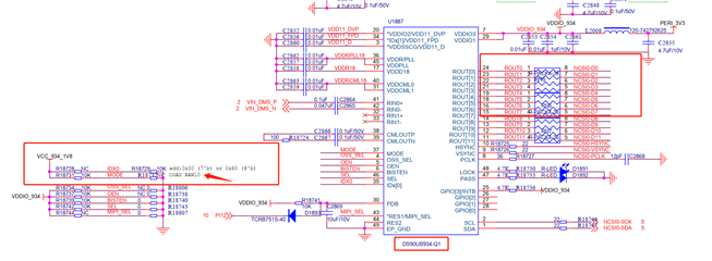
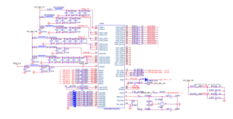
Part Number: DS90UB964-Q1

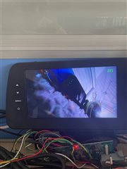
1.The camera has been configured by other manufacturers without the host being configured again, the image: 1280x720 yuv422 10bit;

2. refer to DS90UB96X-Q1EVM User's Guide  config it:

print "CSI_PORT_SEL"
board.WriteReg(0x32,0x01) # CSI0 select
time.sleep(0.1)
print "CSI_PLL_CTL"
board.WriteReg(0x1f,0x02) # CSI0 800mbps
time.sleep(0.1)
print "CSI_EN"
board.WriteReg(0x33,0x1) # CSI_EN & CSI0 4L
time.sleep(0.1)
print "FWD_PORT"
board.WriteReg(0x20,0xe0) # forwarding of RX 0 to CSI0
time.sleep(0.1)
print "FPD3_PORT_SEL"
board.WriteReg(0x4c,0x01) # RX_PORT0
time.sleep(0.1)
print "enable pass throu"
board.WriteReg(0x58,0x58) # enable pass throu
time.sleep(0.1)
board.WriteReg(0x5c,0x18) #
print "SER_ALIAS_ID 0x5c value ", hex(board.ReadReg(0x5c))
time.sleep(0.1)
board.WriteReg(0x5d,0x60) #
print "SlaveID[0] 0x5d value ", hex(board.ReadReg(0x5d))
time.sleep(0.1)
board.WriteReg(0x65,0x60) #
print "SlaveAlias[0] 0x65 value ", hex(board.ReadReg(0x65))
time.sleep(0.1)
print "FV_POLARITY"
board.WriteReg(0x7c,0x01) # FV active low
time.sleep(0.1)
print "YUV422 DT"
board.WriteReg(0x70,0x1f) # VC0 and CSI0 datatype 0x1f yuv422_10b
time.sleep(0.1)
print "FPD_MODE"
board.WriteReg(0x6d,0x7f) # 913A 10-bit mode
time.sleep(0.1)
#########################################################

open: /dev/i2c-1, chip_addr: 0x3d

00 01 02 03 04 05 06 07 08 09 0A 0B 0C 0D 0E 0F
----------------------------------------------------
00 | 7a 00 1e 30 c2 01 00 fe 1c 10 79 79 0f b9 00 ff
10 | 00 00 00 00 00 00 00 00 00 00 00 00 00 00 04 02
20 | e0 03 00 00 00 00 00 00 00 00 00 00 00 00 00 00
30 | 00 00 01 01 00 01 00 03 00 00 00 00 00 00 00 00
40 | 00 a3 01 01 00 00 00 00 00 00 00 00 01 13 55 25
50 | f7 00 00 00 00 00 00 00 58 00 00 ba 18 60 00 00
60 | 00 00 00 00 00 60 00 00 00 00 00 00 00 7f 88 88
70 | 1f 2c e4 02 d0 0c 80 c5 00 01 00 00 01 00 00 00
80 | 00 00 00 00 00 00 00 00 00 00 00 00 00 00 00 00
90 | 00 00 00 00 00 00 00 00 00 00 00 00 00 00 00 00
a0 | 00 00 00 00 00 00 00 00 00 00 00 00 00 00 00 00
b0 | 10 14 1f 08 25 00 18 00 ff 03 03 74 80 00 00 00
c0 | 00 00 00 00 00 00 00 00 00 00 00 00 00 00 00 00
d0 | 00 43 84 0f 60 f8 07 00 00 00 00 00 00 00 00 00
e0 | 00 00 00 00 00 00 00 00 00 00 00 00 00 00 00 00
f0 | 5f 55 42 39 36 34 00 00 00 00 00 00 00 00 00 00

3.capture image:

thank you.

  • Hello Xueze,

    your settings look okay. Please make sure your imager is initialized and configured correctly. 

  • Hi Hamzeh,

    1. the imager is initialized, because test it on 934 parallel input:

        the soc can capture normal image from the 934, I  measure only [D0~D7] have data:

    1)schematic:


    2) I didn't configure 934, use default reg,the data can still be captured normally:

    open 934 device: /dev/i2c-2, chip_addr: 0x30

    00 01 02 03 04 05 06 07 08 09 0A 0B 0C 0D 0E 0F
    ----------------------------------------------------
    00 | 60 00 1e 10 cc 01 00 fe 1c 10 7a 7a 01 b9 28 7f
    10 | 00 00 00 00 00 00 00 00 00 00 00 00 00 00 04 0a
    20 | 30 01 00 00 00 00 00 00 00 00 00 00 00 00 00 00
    30 | 00 00 00 00 40 00 00 00 00 00 00 01 14 6f 00 40
    40 | 00 86 74 01 00 00 00 00 00 00 00 12 00 03 04 25
    50 | 55 00 00 00 00 00 00 00 18 00 00 ba 00 00 00 00
    60 | 00 00 00 00 00 00 00 00 00 00 00 00 00 7f 88 88
    70 | 2b 2c e4 00 00 00 00 c5 00 01 00 00 20 00 00 00
    80 | 00 00 00 00 00 00 00 00 00 00 00 00 00 00 00 00
    90 | 00 00 00 00 00 00 00 00 00 00 00 00 00 00 00 00
    a0 | 02 0f 00 00 08 00 00 00 00 00 00 00 00 00 00 00
    b0 | 08 14 1f 08 25 00 08 00 8f 33 03 74 80 00 00 00
    c0 | 00 00 00 00 00 00 00 00 00 00 00 00 00 00 00 00
    d0 | 00 43 94 05 60 f4 00 00 00 00 00 00 00 00 00 00
    e0 | 00 00 00 00 00 00 00 00 00 00 00 00 00 00 00 00
    f0 | 5f 55 42 39 33 34 00 00 00 00 00 00 00 00 00 00

    3)capture image:


    2. As you can see from the above test, the 934 output is yuv422-8-bit, is the 964-mipi also output

    yuv422-8-bit; the SOC only support 8bit (MEDIA_BUS_FMT_UYVY8_2X8):

    thanks.

  • Hi Hamzeh,

    modify  Raw 10 8-bit mode: 0x7c register[7:6]: 11 : 8-bit processing using lower 8 bits

    capture image is normal;

    now it want to 4 camera input, how config the multiplex.

    thanks.

  • Hello Xueze,

    I can see from the schematic that you are using a Crystal as REFCLK!! Please make sure to use only Oscillator connected to REFCLK input.

    TESTEN pin must be tied to GND.

    For using only 8-bits you need to configure register 0x7C[7:6] correctly.

  • Hi Hamzeh,

    Now I can capture all 4 ch image data;

    How to get whether the camera is plugged in or not, can tell which one is not connected to the camera;

    Which registers should be read.

    thanks.

  • Hello Xueze,

    thanks for the update. Can you share what you have changed to make it working?

    To check if the Camera is plugged or not you will need to monitor each Port's LOCK register.

    For example, for RX0 you need to select Port0 ==> reg 0x4C = 0x01 and then read register 0x4D[0]

    for RX1 you need to select Port1 ==> reg 0x4C = 0x12 and then read register 0x4D[0] ... and so on 

  • Hi Hamzeh,

    modify  Raw 10 8-bit mode: 0x7c register[7:6]: 11 : 8-bit processing using lower 8 bits;

    thanks