This thread has been locked.

If you have a related question, please click the "Ask a related question" button in the top right corner. The newly created question will be automatically linked to this question.

TL16C750E: RX buffer read issue

Part Number: TL16C750E

I am are having difficulty getting the TL16C750E UART to read data correctly.  
The problem looks to be in the internal buffer.
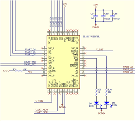
Background:
Test code is initializing the device to operate in a non FIFO, polled mode, with the parity bit code controlled for 9 bit data operation.
If the following initialization sequence is incorrect to achieve that, please let me know how to correct it:

Reset (50us high pulse)
LCR <-- 0xBF
EFR < -- 0x10
LCR < -- 0x83
DLH < -- V1 --+
DLL < --  V2     | -- >1 M BAUD
DLF < --  V3 --+
LCR < --  0xBF
EFR < -- 0x00
LCR < -- 0x03    
IER < -- 0x00
FCR < -- 0x00

A separate board sends incrementing (by 1) byte values ( 9 bit data) at a slow rate (so there is no problem with data over runs), and its code is always started first.
After the above initialization, the TL16C750E test code sends a value to that board to trigger it to start sending its slow data and then polls bit 0 of the LSR, looking for a new received byte:


Read LSR until THR empty is true..
MCR < -- 0x02   (/DTS and /RTS outputs drive LEDs)
LCR < -- 0x2B  ( 9 bit data via code controlled parity bit)
THR < -- data to trigger response
count=0  log detects of new bytes received

forever loop:
 Read LSR until "data in receiver" bit =1
 if true
   increment count
   Read RHR for the data byte
   if  the data >0
     log the data
     log the value of count
   endif
 endif
end of forever loop

What I see in the log results are:
1.  The true data does not start until after reading 128 bytes.  Note:  LSR  "data in receiver" bit correctly updates each time.
     The first 64 are always 0x00, and the next 64 are incorrect, with the first byte of that second 64 close, such as 0xC5,when the true data is 0x05, with increments from 0xC5 on subsequent bytes.

2. If the starting value from the other board is changed, that 128th read value is not correct until:
    a. the TL16C750E test code is run twice
    b. the TL16C750E board is power cycled.


The intent is for the UART to operate in a non-FIFO, polling mode, so according to the data sheet : "If the FIFO is disabled, location 0 of the FIFO is used to store the characters" (section 9.5.2)
But the storage and read internal pointers still seem to be using the entire 128 byte FIFO, vs only using location 0 for both the storage and reading from.

Thanks in advance for you help.

  • Hey KR,

    I'll take a look deeper look at this today and get back to you..

    -Bobby

  • Thanks Bobby.

    Another piece of info is we run the UART interface in full duplex.

  • KR do you have a schematic we can review?

    How is the mode pin of the device biased?

    -Bobby

  • Bobby,

    The mode is pulled to Vcc.

    ...

  • KR,

    The pinout looks good (Matches the datasheet pinout).

    The net names also match the schematic pin names.

    Local decoupling caps on Vcc look good.

    The mode being set to Vcc bias is what I was expecting {This is what we call INTEL mode}. ( I worked with this device before and had issues when I accidentally set the mode to GND while still using the Vcc biased mode then saw bytes rolling over so I was worried you were seeing something similar.)

    The schematic looks okay to me, only minor point is some of the RS485/RS232 inputs like CTS and DSR are floating so you will get some additional leakage due to shoot through currents on the input CMOS stages of these pins.

    ----------------------------------------------------------------

    1) Have you done a loop back test on this device? (short TX to RX and read what you send)

    2) Can you probe the RX pin when you send a byte and verify that you see what you expected? (Maybe show a scopeshot of it)

    3) Can you measure the bit period on the TX pin of the device and compare the bit period with the seperate board's TX to make sure the baud rate isn't mismatched too much?

    4) When you initialize the registers, do you perform a read of the registers after a write to verify the data was written into the registers correctly?

    5) Initialization sequence check

    Reset (50us high pulse)
    LCR <-- 0xBF //8 bits 2 stop bits parity check even forced parity Divisor access enabled //this is set up to enter EFR access
    EFR < -- 0x10 //Enable access to IER[7:4] FCR [5:4] and MCR[7:5]  //this is done to access DLF
    LCR < -- 0x83 // 8 bits 2 stop bits divisor still enabled
    DLH < -- V1 --+
    DLL < --  V2     | -- >1 M BAUD
    DLF < --  V3 --+
    LCR < --  0xBF //8 bits 2 stop bits parity check even forced parity Divisor access enabled //this is set up to enter EFR access
    EFR < -- 0x00 //turn off access to special registers and sets normal operations of RTS and CTS
    LCR < -- 0x03    // 8 bits 2 stop bits
    IER < -- 0x00 // disable INTs (INT not used based on schematic, polling is the method for checking INTs through LSR if done this way)
    FCR < -- 0x00 //DMA0 mode, FIFO disabled

    "A separate board sends incrementing (by 1) byte values ( 9 bit data) at a slow rate (so there is no problem with data over runs), and its code is always started first."

    Just to be double sure here, the LCR value has 8 bit data plus 2 stop bits and a start bit so the total byte format is 11 bits. Is the 9 bit you mentioned a typo?

    -Bobby

  • Thanks for your reply Bobby.

    Your Mode pin bias mistake:  We've all been there-- some of us at least twice :-)

    Items 1--> 3: The receiver input signals are ok.

    After the TL16C750E is initialized and the trigger cmd byte sent, the other board gets the cmd and just keeps sending incrementing reply bytes (presently starting with 0x07).  The TL16C750E code presently stops after the LSR bit 0 check has detected 650 bytes and stored the subsequent reading of  RHR (regardless of value).  The log shows the correct value of the first byte (0x07) sent, is in the 128th read of RHR. And all subsequent data is correct-- 0x08 in the 129th read, 0x09 in the 130th read, etc.  If there was anything off in the BAUD rate or stop bits, the UART would never read so many bytes correctly.  So the bytes are there, it's just the RHR pointer is in the wrong location.

    Item 4:  Good suggestion-- thanks for the reminder to "trust but verify". 

    Result: all register verifies are ok except FCR.  Its Enable FIFOs bit 0 is cleared in the write of 0x00, but the read is 0x01.  The data sheet says FCR is a write only register, so the read results should be questionable at best.  However, the 0x01 read does correspond to the apparently still active FIFO.  Again, from what I've understood from the data sheet, FIFOs should be disabled with that initialization, and only FIFO index [0] should be filled and subsequently read from.  The device is acting like the first storage is at Rx FIFO index [0], and the first read from Rx FIFO index[1], with both storage & read pointers incrementing from there on subsequent byte receives.

    Item 5: My typo.  LCR (after EFR <-- 0x00) is actually initialized to 0x2B for 8 bit data and 1 stop bit, and initial control of the parity bit to generate 9 bit data. 

  • all register verifies are ok except FCR.  Its Enable FIFOs bit 0 is cleared in the write of 0x00, but the read is 0x01. 

    So this means that the FIFOs are definitely disabled from the read. When you read address 0B010 it shows IIR and bits 7 and 6 of IIR reflect the FCR bit 0 value. The 0x01h you're reading implies there is an INT asserted which I assume we ignore since INT isn't being used in your setup.

    I'll probably need to see if I can get a hold of one of the EVMs for the device and try to see if I can replicate what you're seeing by trying to follow your initialization steps. I'll let you know on Friday about if I was able to get a hold of the EVM.

    By the way, how repeatable is the issue? Have you tested with only 1 board/unit? Does the problem follow the unit? Have you replaced the 'bad working board' with a new device to see if the problem reoccurs? 

    -Bobby

  • The issue looks to be resolved. 

    The device reading the UART had some buffering issues in its reads.  The program was actually making several physical reads to get one reading.  The reads now look better and usable, but there still is a minor mystery.  If  FIFO use is disabled, should not the internal pointer always read from FIFO[0] as the data indicates?

  • Hi KR,

    Glad to see you were able to resolve the problem. 

    The reads now look better and usable, but there still is a minor mystery

    Does better mean that the issue is completely gone or are you still seeing a few 0x00h before finally getting the expected characters?

    If  FIFO use is disabled, should not the internal pointer always read from FIFO[0] as the data indicates?

    Yes, you should be reading from that register if the FIFO is disabled.

    -Bobby

  • I think for now we can declare victory. 

    The TL16C750E is driven by a parallel port peripheral vs a true parallel port, and it is buffered.   The test code reads twice to get a value from the pins into the program code.  Both reads generate physical bus cycles. The two (vs previous too many) read technique is working, but the final version I think will change that second read to use an out of UART range address, just in case reading the RHR twice causes an unforeseen issue..

    No FIFO at this stage, but if that is used later, such single physical reads are likely the best.  If later issues arrive when using the FIFOs, I'll re-post.

    Thanks again for all your help Bobby.