This thread has been locked.

If you have a related question, please click the "Ask a related question" button in the top right corner. The newly created question will be automatically linked to this question.

TCA9545A: debug TCA9545A based on RK3399

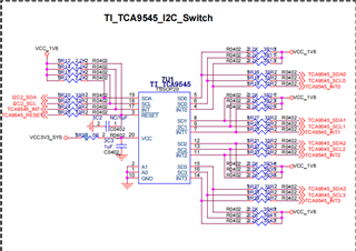
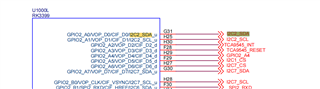
Part Number: TCA9545A

Now we are debugging TCA9545A based on RK3399. At present, we only know how to open the access I2C, but we do not know how to work and whether a driver is needed. If necessary, could you help to provide Linux driver and configuration?

thanks

  • The device tree configuration is similar to any other I²C mux, with:

    compatible = "nxp,pca9545"
  • Referring to PCA9548, I did not find the I2C address in TCA9545. Is there no i2C address in tCA9545?

  • i2c-mux@74 {
    compatible = "nxp,pca9548";
    #address-cells = <1>;
    #size-cells = <0>;
    reg = <0x74>;

  • As shown in section 8.6.1 of the datasheet, the TCA9545A has the address 0x70/0x71/0x72/0x73, depending on the address pins. Why are you mentioning the PCA9548, which is a different device?

  • Now I can only refer to pCA9545 configuration, now i2C-MUx-PCA9541.c modified as the driver, there are several more devices under /dev/i2c, but I hung i2C-sensor under several generated devices, there is no effect, I feel that the chip does not work at all

    Is there something wrong with my configuration?

    + tca9545@73 {
    + compatible = "tca9545";
    + #address-cells = <1>;
    + #size-cells = <0>;
    + reg = <0x73>;
    + interrupt-parent = <&gpio2>;
    + interrupts = <2 IRQ_TYPE_LEVEL_LOW>;
    + interrupt-controller;
    + reset-gpios = <&gpio2 3 GPIO_ACTIVE_HIGH>;
    + #interrupt-cells = <4>;
    +
    + i2c@1 {
    + #address-cells = <1>;
    + #size-cells = <0>;
    + reg = <1>;
    + tsl2562@29 {
    + compatible = "grove,tsl2561";
    + reg = <0x29>;
    + };
    + };

    root@linaro-alip:~# i2cdetect -l
    i2c-0 i2c rk3x-i2c I2C adapter
    i2c-1 i2c rk3x-i2c I2C adapter
    i2c-2 i2c rk3x-i2c I2C adapter
    i2c-4 i2c rk3x-i2c I2C adapter
    i2c-7 i2c rk3x-i2c I2C adapter
    i2c-9 i2c i2c-2-mux (chan_id 0) I2C adapter
    i2c-10 i2c i2c-2-mux (chan_id 1) I2C adapter
    i2c-11 i2c i2c-2-mux (chan_id 2) I2C adapter
    i2c-12 i2c i2c-2-mux (chan_id 3) I2C adapter
    i2c-13 i2c DesignWare HDMI I2C adapter
    i2c-14 i2c DP-AUX I2C adapter
    root@linaro-alip:~#

  • Shouldn't the compatible entry be "nxp,pca9545"?

    I do not know your board. Please show a schematic of the I²C parts.

  • i2c-mux-pca954x.c
    Fullscreen
    1
    2
    3
    4
    5
    6
    7
    8
    9
    10
    11
    12
    13
    14
    15
    16
    17
    18
    19
    /*
    * I2C multiplexer
    *
    * Copyright (c) 2008-2009 Rodolfo Giometti <giometti@linux.it>
    * Copyright (c) 2008-2009 Eurotech S.p.A. <info@eurotech.it>
    *
    * This module supports the PCA954x series of I2C multiplexer/switch chips
    * made by Philips Semiconductors.
    * This includes the:
    * PCA9540, PCA9542, PCA9543, PCA9544, PCA9545, PCA9546, PCA9547
    * and PCA9548.
    *
    * These chips are all controlled via the I2C bus itself, and all have a
    * single 8-bit register. The upstream "parent" bus fans out to two,
    * four, or eight downstream busses or channels; which of these
    * are selected is determined by the chip type and register contents. A
    * mux can select only one sub-bus at a time; a switch can select any
    * combination simultaneously.
    *
    XXXXXXXXXXXXXXXXXXXXXXXXXXXXXXXXXXXXXXXXXXXXXXXXXX

  • Above is the schematic diagram and Linux driver. I mounted a sensor on the generated I2C bus, but it didn't seem to work

  • VCC is too high. Section 9.2.1 of the datasheet says:

    The pass-gate transistors of the TCA9545A are constructed such that the VCC voltage can be used to limit the maximum voltage that is passed from one I²C bus to another.

    Figure 17 shows the voltage characteristics of the pass-gate transistors. In order for the TCA9545A to act as a voltage translator, the Vpass voltage must be equal to or lower than the lowest bus voltage. For example, if the main bus is running at 5 V and the downstream buses are 3.3 V and 2.7 V, Vpass must be equal to or below 2.7 V to effectively clamp the downstream bus voltages.

    As shown by the Vpass specification in the electrical characteristics table, to keep the switch output voltage below 1.8 V, VCC must be no higher than 2.7 V. You can simply use VCC = 1.8 V.

    If that still does not work, check with an oscilloscope whether the I²C signals arrive correctly at the upstream and downstream buses.