This thread has been locked.

If you have a related question, please click the "Ask a related question" button in the top right corner. The newly created question will be automatically linked to this question.

DP83848M: additional precautions for PoE needed?

Expert 1915 points
Part Number: DP83848M
Other Parts Discussed in Thread: TPD4E05U06

Hello,

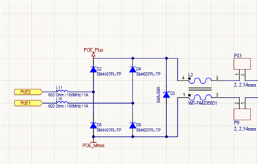
we're using the DP83848M in a PoE powered device. It's connected to a PoE capable transfomer like this:

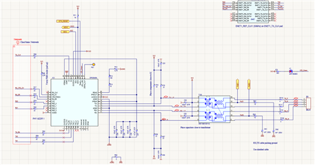
The raw PoE power is then further processed by a bridge rectifier and filtering to make 5V DC (and from there on all the voltages required)

In the production we see the following failure in an alarming quantity: the Ethernet PHY does not work anymore (OS report no link). It's still visible to the host, the registers can be read and written (MDIO access). So the PHY part that talk to the MAC works fine, but there is no link established. Replacing the PHY solves the issue.

The PHY datasheet shows the following parameters:

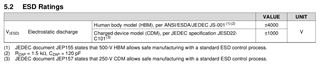
I assume they also apply to the RX/TX pins of the PHY. We might have some PoE related transients (plug/unplug events? The scope does show spikes well above 10V) - but will they cause any harm on the secondary side?

Is my circuit between PHY and transformer sufficiently robust?

We did find a few instances where due to improper soldering the center tap of one of the two coils on the secondary side was not properly manufactured - but I'd expect that to just give no link, no to damage the PHY transceiver.

Best regards,

Lo

  • Hello,

    I am in contact with the proper resources regarding this topic.

    Sincerely,

    Gerome

  • Hi,

    normally the transformer is the only critical part you need. The one you are using should be fine, there is no additional filtering required for functionality. How where the spikes measured, between which pins do you see them? I don't think these spikes killed the PHY.

    What exactly are you using to inject power? What standard are you using? Power Class? Voltage and current?

    Normally you should be able to short the center taps on the primary side, without any negative impact on the link. If this is not the case with power on and current flow, I would check if the current flow is too high and the transformer might be saturated. 

    Best regards,

    Steffen

  • Hello Steffen,

    We measured 10Vpp using a 200MHz scope between RX+/-  or TX+/-. Multiple connect attempts are required to capture the spikes.

    We use a PoE power injector, in production TP-Link TL-SF1005P units are used, the cable length varies but is less than 20m in this setup.

    We specify the following operating conditions for our device, it's by no means power hungry:

    ● Power via Ethernet according to IEEE802.3af/at/bt Mode A (phantom power)
    ● PoE class 3, up to 12.95W
    ● DC voltage range (PoE): 36-57 VDC
    ● DC maximum current (PoE): 400 mA
    ● Average power consumption: 2.5W

    Since we have only four wires that are physically connected, the use of the data pair is mandatory (mode A).

    PoE on the device side is implemented with a MAX5995B PoE controller, after plugging the cable the PoE controller will have to negotiate before he turns on the subsequent DC/DC (5V) which then delivers power to another DC/DC (3.3V) that power the DP83848M. So there is a significant delay and the spikes appear when the PHY is not yet powered. This delay also depends on the switch used (I use an allied telesis which seems pretty slow)

    We're considering an additional TVS diode type Würth 82400152 (https://www.we-online.com/catalog/en/WE-TVS-HS) for the secondary side RX/TX pair. But unless I know the root cause this might not be necessary nor solve the issue. The datasheet does not show an equivalent circuit for the TX/RX pins so I'm unsure what protection to add, if any.

    We have found a few unconnected center taps on the secondary side for the RX pair, but I'd expect this error to just have transmission errors, not to fry the PHY. (Probably unrelated issue caused by improper soldering, was only found after visual inspection).

    Best regards,

    Lo

  • Hi Lo,

    thanks for the additional information. the 10 Vpp you are measuring are typically coupling from the cable side to the PHY side through a capacitive way. Such a transformer always has a little bit of capacitance between primary and secondary winding.

    It should not be needed to have TVS diodes there, but it also don't hurt and would eliminate the spikes you are seeing. Here I would use TPD4E05U06 but the ones you mentioned should also be ok.

    You are using a commercial PoE PSE, so I would assume this is functional and not causing problems. The current ratings you have given also don't exceed the current allowed by the transformer.

    Are only the devices where the center tap was not soldered properly damaged and non functional? Is this system working in general but only a few devices are failing?

    Best regards,

    Steffen

  • Hi Steffen,

    we do have a few failing units in the field, I have not received them yet. Of our prototypes we keep here none failed.

    From the current production batch a significant amount have non-functional Ethernet due to a damaged PHY. I don't know if they correlate with the improperly soldered transformers, but at least some do. A few units are on the way to me.

    Is there a chance that a missing center tap connection (to 3.3V) will damage the PHY? That would explain a lot.

    Best regards,

    Lothar

  • Hi,

    would be interesting check the failed units if the middle tap is disconnected as well. With middle tap connected there cannot be a high voltage between RX and TX pair on the PHY side. 

    If the middle tap is disconnected, there can be a voltage, but I would assume the current to be pretty low and not to be able to damage the transceiver of the PHY.

    Maybe you can measure the diode voltage on the RX and TX pins between the 3.3 V as well as GND and check if this is different between the functional and the non functional units. I would assume if there is a damage due to high voltage or reverse voltage it will kill the ESD structures and you will be able to measure a short or open.

    I will check internally if there is something known about what happens if the middle tap is disconnected.

    Best regards,

    Steffen

  • Hi,

    The 10 V you have seen on the RX and TX lines are enough to damage the Phy. It needs to be prevented that this can happen.

  • Hi Steffen,

    thanks, we'll add circuitry to prevent this.

    Best regards,

    Lo