This thread has been locked.

If you have a related question, please click the "Ask a related question" button in the top right corner. The newly created question will be automatically linked to this question.

TPD2E009: Can TPD2E009 be used for several hundred kHz RS-485 application?

Part Number: TPD2E009
Other Parts Discussed in Thread: TPD2E007, AM26C31, AM26C32, STRIKE, THVD1552

Hi Team, 

My customer is considering use TPD2E009 to connect differential output of AM26C31INSR. He has following 2 questions, could you kindly help? Thanks.

1. Can TPD2E009 be used for RS-485 application? Communication speed is several hundred kHz. 

    BTW, I saw ESD protection IC selection guidance recommended TPD2E007 for RS-485 application, and I saw the difference between TPD2E009 and TPD2E007 is uni-directional and bi-directional. 

    Does it mean bi-directional is necessary for RS-485 application?

2. Is it okay to connect  AM26C31INSR's output with TPD2E009DBZR's D+ and D-? 

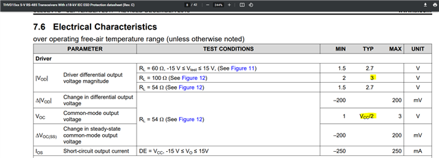
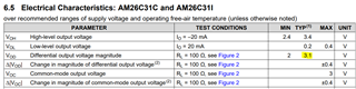
From  AM26C31INSR's datasheet, VDO is 3.1V. 

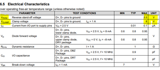
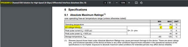
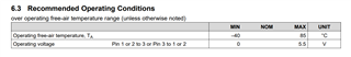
And from TPD2E009's datasheet, operating voltage is range from 0V to 5.5V. 

So I think 3.1V VDO is inside the range, TPD2E009 can be used here. Am I understanding it correct? Or VDO needs to double so should be 6.2V?  


Thanks.

Regards,

Jo

  • Hi Jo,

    Please see my answers to your questions, below:

    1. I would not recommend using TPD2E009 in an RS-485 application. A bidirectional diode is needed since the signal voltage oscillates between positive and negative values. That is why TPD2E007 is a better fit.
      1.  
    2. The D+ and D- pin on TPD2E009 are labelled as such because this device is primarily used to protect USB interfaces. However, there is no difference in functionality between the two pins. You can think of them as being labelled as "IO1" and "IO2" instead of "D+" and "D-".

    For the operating voltage levels, you need to consider the common mode voltage as well. If you have a differential voltage between A and B of 4 V but also have a common mode voltage of 3 V, then highest operating voltage level will actually be 7 V with respect to ground. A 5.5 V diode like TPD2E009 would start conducting prematurely in this case. That's why a 14 V diode like TPD2E007 is recommended.

    Please let me know if you have any other questions. 

    Regards,

    Matt Smith

  • Hi Smith, 

    Thank you for the reply. I understood TPD2E007 works better here. 

    I have some questions for RS-485, maybe I should ask RS-485 team. But please advise me if you have expertise on it. 

    1. Based on Figure 3. from this E2E thread, I think MAX Vout of AM26C31INSR will be VOS+(VDO/2)=3+4/2=5V instead of 7V you mentioned. Am I understanding it wrong? 

    2. In above case, I think the voltage range apply to ESD IC will be 1V(3-4/2)~5V(3+4/2). In this case, since output is only positive value, can single directional ESD IC TPD2E009 be used? 

    Thanks.

    Regards,

    Jo

  • Hi Jo,

    I will transfer this thread to the RS-485 transceiver team to answer your first question on operating voltage levels. 

    With regards to your second question, I would agree that if the voltage levels with respect to ground stay between 1 V and 5 V, then TPD2E009 would work.

    Regards,

    Matt 

  • Hi Jo,

    1. Based on Figure 3. from this E2E thread, I think MAX Vout of AM26C31INSR will be VOS+(VDO/2)=3+4/2=5V instead of 7V you mentioned. Am I understanding it wrong? 

    Your math is correct but I don't know where you got the 4V in your case. I calculated Vos = Voc = 3V, and VDO = VOD = 3.1V. So then I would have calculated a [3V + (3.1V / 2)] = 4.55V. I think in Matt's explanation, he was using hypothetical numbers not necessarily associated with the specs of AM26C31 device. 

    2. In above case, I think the voltage range apply to ESD IC will be 1V(3-4/2)~5V(3+4/2). In this case, since output is only positive value, can single directional ESD IC TPD2E009 be used? 

    I can think of a couple reasons why you may want to use TPD2E007 instead of TPD2E009 for RS485 applications. 

    Even with the cases you describe of seeing only positive voltages the VOL (low-level output voltage) spec of the AM26C31I is typical of 0.2V. Yes this voltage is positive, the voltage may also ring at this level possibly going below GND at times. You can see this affect in the figure that Matt provided in his earlier response. 

    Seeing that the "Y" voltage (non-inverting output of your differential signal) is roughly at 0V, you can see that the slight ringing dips below 0V at times. This ringing affect can also be magnified depending on the signal frequency. 

    I looked at the abs. max specs of the TPD2E009 and I would be afraid to push the device below the 0V spec.

    I can also think of another reason for using the TPD2E007 over the TPD2E009 because of the common mode difference between your transmitting and receiving RS485 device. Most RS485 applications transmit over some length of cable ranging from a few meters to 100's of meters. This distance of cable can create a GPD (ground potential difference) which could push your voltage on D+ and D- pins below or above ground by this GPD which could break the TPD2E009 by going above or below its abs. max I/O voltage tolerance (I think this was what Matt was getting at in his response above). RS485 compliant transceivers are expected to withstand common-mode voltage ranges from -7V to +12V. 

    This is the reason I would suggest that TPD2E007 be used for RS485 applications due to its wide range of operating voltage: -13V < VIO < 13V. 

    Best Regards,

    Tyler

  • Hi Tyler, 

    Thank you for the detailed explanation!

    I understood TPD2E007 is a better option here because of IO voltage tolerance. 

    Customer said the Y, Z output pin of AM26C31INSR he measured was between 0V~3V, based on Matt's comment I think TPD2E009 should also work here. (I understand the ringing affect may cause problem if negative voltage is applied)

    However, I would like to confirm with your comment for GPD. 

    I'm not sure if I should ask you or Matt, will RS485 Receiver also need a ESD protection IC if ESD protection IC is implemented on RS485 Driver side? 

    If so, I think even TPD2E009 can be used for driver side with customer's measure result, IO voltage tolerance of TPD2E009 may be violated due to GPD for receiver side. 

    Thanks.

    Regards,

    Jo 

  • Hi Jo,

    I'm not sure if I should ask you or Matt, will RS485 Receiver also need a ESD protection IC if ESD protection IC is implemented on RS485 Driver side?

    This is dependent of the grounding differences in the system. Say you have a RS485 transceiver communicating with another RS485 transceiver at a distance of ~1m. Since the distance is short, the ground potential difference (GPD) is probably not that much. So a singular ESD protection device would suffice. In another case, you have the same two RS485 transceivers, but now you are communicating at a distance of 500m. The grounds are probably resting at different voltages, and therefore you have a much more significant GPD. In this case, it would be a good idea to include ESD protection IC's at both transceivers if you are communicating both directions (RS485 is bi-directional communication protocol).

    If you are using TPD2E009 on both sides, I could see this as a problem due to its limited abs. max I/O voltage tolerance of 0V <-> 6V range. If the AM26C31INSR sends a HIGH of 3V on "Y" and a LOW of 0V on "Z", then your differential voltage is 3V. But if you have a GPD that is 5V at the receiving end of another transceiver, you now have a HIGH signal that looks like 3V + 5V = 8V, and a LOW signal of 0V + 5V = 5V. Differential is still 3V, but your HIGH and LOW signals are level shifted up a common mode voltage, which could easily push outside abs. max conditions of the TPD2E009. This is why I would recommend the TPD2E007 because it accounts for these common mode shifts.

    Regards,

    Tyler

  • Hi Tyler, 

    Thank you for the explanation. 

    Customer is now thinking add TPD2E007 to input pin of AM26C32(receiver). 

    However, the ab. max value of input voltage is -11V to 14V for AM26C32 and recommended VIO range is -13V to 13V for TPD2E007.

    So customer have one question that, when -12V~-13V is applied, won't AM26C32 break first before TPD2E007's protection activate? 

    Thanks.

    Regards,

    Jo

  • Hi Jo,

    This is a good point. abs. max input voltage to the AM26C32 pins is -11V to 14V while recommended VIO range for TPD2E007 is -13V to 13V. So if a sustained voltage of ~-12V was applied to the inputs, the AM26C32 would fail before the TPD2E007. It is off by about 2 volts in the negative range for full protection. The TPD2E007 would shunt current quickly in the case of an ESD strike, but looking at the datasheet I do not see a specific clamping voltage that would suppress a -~12v signal. 

    Another TVS diode that we usually recommend customers for RS485 applications is the SM712 TVS diode array by LittleFuse. I have linked the datasheet here.

    Regards,

    Tyler

  • Hi Tyler,

    Thank you for the relay.

    So you’re saying that TPD2E007 is not suitable for ESD protection for AM26C32 if sustained voltage below -12V is expected to be applied, right?

    And since VRWM of SM712 is 7V for negative voltage event, SM712 will clamp voltage to -7V if voltage below -7V is applied to input of AM26C32, correct?

    Thanks.

    Regards,

    Jo

  • Hi Jo,

    TPD2E007 is not suitable by about -2V in the negative voltage range, but protects positive over-voltages. To have an ESD transient protection device that protects the full input range to the AM26C32, the protection devices needs to have lower input abs. max values so it burns up first or have voltage clamping capability that protects the AM26C32. 

    And since VRWM of SM712 is 7V for negative voltage event, SM712 will clamp voltage to -7V if voltage below -7V is applied to input of AM26C32, correct?

    That is the working voltage in which the device is designed to conduct small amounts of current, but allow RS485 data to transmit effectively. The clamping side of things occurs at breakdown voltage range shortly after. This is described in the datasheet:

    SM712 will conduct significant amounts of current at <-7.5V and >+13.3V. So as over-voltage events occur, the SM712 will sink the current making sure it doesn't reach the AM26C32, therefore protecting the device. SM712 also has ESD protection that complies with IEC 61000-4-2 standard. 

    Regards,

    Tyler

  • Hi Tyler, 

    Thank you for the explanation! I understood that TPD2E007 can't be used for protection for negative side of AM26C32 due to the voltage range. 

    And I understood SM712 can be used if input voltage to AM26C32 is ranging -7V~12V. 

    Hi Matt, 

    Do TI have other ESD protection solution that works with AM26C32?

    Based on the discussion with Tyler, since abs. max rating of AM26C32 is -11V~14V, in the other hand, the abs. max rating is -13V~13V for TPD2E007. So AM26C32 will be broken first before TPD2E007 works if -12V is applied. 

    Thanks.

    Regards,

    Jo

  • Hi Jo,

    TPD2E007 breakdown voltage doesn't protect the AM26C32. If we look at the breakdown voltage curve below, we see that breakdown voltage ~+-17V meaning that we will reach abs. max conditions on AM26C32 before TPD2E007 starts to conduct significant current. 

    I reviewed the SM712 datasheet and noticed that the clamping specifications do not entirely protect the AM26C32. 

    Working voltage is -7V to +12V which is plenty room for AM26C32 given that RS422 signals swing roughly 0V to 5V. 

    Breakdown voltage is -7.5V to +13.3V which would begin to protect AM26C32 due to over-voltage event.

    Here is where my concern lies:

    Clamping voltage is -11V to +19V. If for example a +18V strike would occur, the AM26C32 may be damaged because the SM712 wouldn't clamp in time to protect the device. 

    What we need to do is to find a protection device that clamps before the abs. max conditions of the AM26C32. 

    I am looping in MPD to find a protection device that would be suitable. I know Matt is currently out of office. You can expect a response sometime next week.

    Regards,

    Tyler

  • Hi Jo, Hi Tyler -

    Assuming RS485 signals swing roughly 0V to 5V - and assuming you are looking to protect D+ and D-; TPD2E009 will be suited to protect the AM26C32 transceiver, as the voltage clamping of TPD2E009 is 8V max, which is lower than the abs maximum of the AM26C32 device.

    If you are looking to protect a signal that will swing >5V then you need a different device.

    Unfortunately, TPD2E007 is the only TI device which can protect signals up to 13V.  We are working on a family of mid-voltage devices and we should have more to offer in the near future.

    Please let me know if you have further questions.

    Thanks,
    Erika

  • Hi Tyler, Erika,

    Thank you for the reply. Let me organize customer's system configuration and let me clarify my questions again. 

    Customer uses AM26C31 and AM26C32 to communicate with receiver and driver side of THVD1552 respectively. 

    Customer is considering add ESD protection IC to output of AM26C31 and input of AM26C32. 

    Based on above config, customer wants to know following : 

    1. What is the best ESD protection IC for AM26C31? I think TPD2E007 fits here. 

    2. What is the best ESD protection IC for AM26C32? I think TPD2E009 fits here. But I have concern that Tyler mentioned before. Since VIL of AM26C32 is 0V~0.8V, TPD2E009 may be broken if signal is below 0V even for only short time period. Will it be a problem here?

    Thanks.

    Regards,

    Jo

  • Hi Jo,

    Thanks for providing a clear summary.

    -- Agree on #1.

    -- As far as #2, TPD2E009 should work.  If VIL is 0 ~0.8V, and if signal goes below 0 for a very short time period it shouldn't be a problem.  The input level could be down a bit, technically down to about -0.6V without issue.   The process does have a bit of margin for this.

    Hope this helps,

    Erika

  • Hi Erika, 

    Thank you for the reply. 

    Regarding #2, I understood and I'll recommend TPD2E009 for AM26C32 to customer. 

    Regarding #1, based on the answer on #2, can TPD2E009 also be able to used for AM26C31 if VOL of AM26C31 is 0.2V~0.4V? Since customer wants to use same ESD protection device if it's possible, so let me double check. If it's risky, I'll recommend TPD2E007 for AM26C31 to customer.

    Thanks.

    Regards,

    Jo

  • Hi Jo,

    Due to potential common mode voltage differences between two transceivers, I would not recommend TPD2E009 for the AM26C31. I believe TPD2E007 is your best bet for protecting the bus lines on AM26C31 due to its breakdown voltage operating range and its ESD surge protection ratings. Even with common mode shifts, TPD2E007 will continue to let signal data pass through, while protecting the bus from high-voltage events. 

    Regards,

    Tyler

  • Hi Tyler, 

    Sorry for the typo above, customer is using THVD1552 with AM26C31 and AM26C32. 

    I understood AM26C31 should use TPD2E007 for ESD protection. 

    For AM26C32, though Erika said TPD2E009 should be okay here, but I still have question. 

    If my understanding is correct, when AM26C32 receive signal from THVD1552, I think the VID that A pin and B pin of AM26C32 get will be 1V and 4V respectively. (Assume VCC=5V). 

    When the distance between driver of THVD1552 and AM26C32(receiver) is long(i.e. several hundred meters), isn't there any chance that voltage will become negative value due to common mode voltage caused by GPD? 

    In this case, negative voltage will exceed abs. max rating of TPD2E009, which may cause TPD2E009 broken. So I'm still doubtful if TPD2E009 can be used for ESD protection for AM26C32 or not. 

    I would like to know if it is no problem to use TPD2E009 for ESD protection for AM26C32, could you kindly help double-check?

    If possible, let's talk via Webex. Please correct me if I have any misunderstanding with RS422. 

    Thanks.

    Regards,

    Jo

  • Hi Jo,

    Erika only recommended TPD2E009 under the assumption that the voltage would only swing between -0.6 to 6 V. However, like Tyler said in his last reply, common mode shifts do happen, and this would cause the voltage to go outside the acceptable range for TPD2E009. Therefore, TPD2E007 is the best choice for both transceivers. 

    Regards,

    Matt 

  • Hi Matt,

    Thank you for the comment. 

    I want to ask, 

    Let me summarize the answer above, please help confirm if my understanding is correct or not. 

    1. TPD2E007's abs. max rating is -13.5V~13.5V so it can fully protect abs. max rating range(-14V~14V) of AM26C31. Which means, TPD2E007 can work with AM26C31 without any limitation.  

    2. TPD2E007 can't protect full abs. max rating range(-11V~14V) of AM26C32, which means TPD2E007 can't be used with AM26C32. To protect full abs. max rating range(-11V~14V) of AM26C32, customer needs to select other ESD protection device that have narrower abs. max rating range than AM26C32.  

    Finally, I have one question want to clarify. 

    Is the AM26C32's abs. max rating -11V~14V, defined for DC voltage? 

    I mean, if voltage lower than -12V is applied to AM26C32 during ESD event, AM26C32 itself should be safe without external ESD protection IC? 

    What I want to ask is that, if customer don't apply DC -12V to AM26C32, TPD2E007 can work for ESD event protection with AM26C32, right?

    Thanks.

    Regards,

    Jo

  • Hi Jo,

    You are correct on #1. For #2, TPD2E007 will still work. Since the -11 V to 14 V operating range of AM26C32 is within the TPD2E007 operating range, TPD2E007 will not burn up. I recommend watching this video on working voltage to clarify your understanding: https://training.ti.com/esd-essentials-esd-working-voltage?context=1136983-1139548-1135651 . In the TPD2E007 datasheet, Vrwm is not explicitly stated, but can be correlated to the abs max spec. 

    In regards to your final question, yes, that is the DC abs max for AM26C32. For most datasheets, unless it is specified as a "transient abs max", the abs max voltage is for constant DC voltages. So if you applied -12 V to AM26C32 for a few nanoseconds, it should fine due to the internal ESD cell of the device. However, if you apply -12 V for an extended period of time, the AM26C32 would fail. 

    Regards,

    Matt 

  • Hi Matt, 

    Thank you for the reply. I understood. Customer wants to confirm one thing. 

    You said, "So if you applied -12 V to AM26C32 for a few nanoseconds, it should fine due to the internal ESD cell of the device." 

    From Figure 2. of TPD2E007 datasheet, ESD event lasts for at least 180ns and voltage under -20V is applied during that.

    AM26C32 will not be broken even for several hundred nanoseconds, right?

    https://www.tij.co.jp/jp/lit/ds/symlink/tpd2e007.pdf#page=5

    Thanks.

    Regards,

    Jo

  • Hi Tyler, 

    I want to confirm 2 things. 

    1. The abs. max rating of Y, Z pin of AM26C31 is defined as Vo, which is -0.5V~7V respectively, right? 

    2. If abs. max rating of output pin(Y,Z) of AM26C31 is ranging -0.5V~7V respectively, even voltage on Y,Z pin exceeds -0.5V~7V in ESD event, AM26C31 should be safe, right?

    Thanks.

    Regards,

    Jo

  • Hi Jo,

    I can't confirm that since the AMC26C32 datasheet doesn't explicitly state a transient abs max, but I think it should work. 

    Regards,

    Matt 

  • Hi Jo,

    Thank you for your questions.

    1. The abs. max rating of Y, Z pin of AM26C31 is defined as Vo, which is -0.5V~7V respectively, right? 

    Yes. Given that this is a very old part, abs. max conditions for Y,Z pins are not explicitly listed. We must look at maximum output voltage which is -0.5V ~ 7V for break condition for a single pin. 

    2. If abs. max rating of output pin(Y,Z) of AM26C31 is ranging -0.5V~7V respectively, even voltage on Y,Z pin exceeds -0.5V~7V in ESD event, AM26C31 should be safe, right?

    Internal ESD protection of AM26C31 may or may not protect against a given ESD strike that exceeds the -0.5V ~ 7.0V range - it depends on time of the transient and voltage level of the transient. We can be more certain that the device will survive if we implement external ESD protection circuitry. However, if you had a 8V DC signal on Y or Z for seconds at a time, then you are potentially damaging the device unless you have some external protection to clamp the voltage before the abs. max rating.

    Regards,

    Tyler

  • Hi Matt, Tyler, 

    Thank you for the comment and explanation! 

    Let me check my following understanding with you. 

    Let's say customer uses TPD2E007 for AM26C31 and AM26C32 for ESD protection. 

    TPD2E007 will absorb current(energy) during ESD event, so even high voltage applied to AM26C3x that's exceeding its abs. max rating(since it is parallel to TPD2E007),

    since there is little current flow through AM26C3x(which means no much energy applied to AM26C3x), it will not cause problem for AM26C3x even when high voltage applied during ESD event. 

    Is my understanding correct?

    Thanks.

    Regards,

    Jo

  • Hi Jo,

    TPD2E007 will absorb current(energy) during ESD event, so even high voltage applied to AM26C3x that's exceeding its abs. max rating(since it is parallel to TPD2E007),

    since there is little current flow through AM26C3x(which means no much energy applied to AM26C3x), it will not cause problem for AM26C3x even when high voltage applied during ESD event. 

    I believe your understanding is correct. Stand alone AM26C3x devices may or may not receive permanent damage from an ESD strike outside abs. max ratings. Therefore, adding external protection circuitry such as the TPD2E007 provides added over-voltage protection to devices on the bus. In the event of high-voltage event, there is a large amount of current which must be directed. Instead of pushing the current through the transceivers, the TPD2E007 takes the majority of current flow, hopefully saving AM26C3x from high electrical stress which could damage the devices. 

    Regards,

    Tyler