This thread has been locked.

If you have a related question, please click the "Ask a related question" button in the top right corner. The newly created question will be automatically linked to this question.

DP83825EVM: Creating repeater from two eval boards

Part Number: DP83825EVM
Other Parts Discussed in Thread: DP83825I

This is actually a continuation of another thread that I had started and has since been locked.  I'm not sure why.  The problem was not resolved and not that much time had elapsed.

https://e2e.ti.com/support/interface-group/interface/f/interface-forum/1055150/dp83825evm-interface-forum/3930157

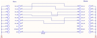
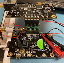
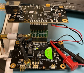
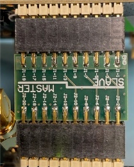
When the above thread was last active, I had been unable to connect two EVM boards together to form a repeater per the available application info for the chip and eval board.  After numerous back-forths in the previous forum thread and a TI tech support phone call, it was suggested that I create a custom, impedance matched, trace length matched interface between the two EVM boards so as to try to maximize RMII signal integrity.  I feel that I was able to do that and a pic of the result is below.  In the end, it is still not working even after trying both a "MASTER>SLAVE" and "SLAVE>SLAVE w/ext 50MHz clock" configurations. I can still not get a 10/100Base-T connection to go through.  All symptoms are the same as before (previous thread where I was using a homemade cable connection). 

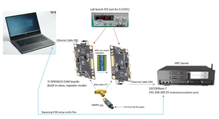
I first tried connecting a master configured board to a slave configured board and fed the master's 50MHz clock output to the slave.  No joy.  Then I connected two slaves together and fed an external clock to both. Clock specs: 25ppm, 2.5nS rise, 1pS jitter.  Nothing.  I tried resetting one and/or both boards on multiple occasions after power up.  

I have both (slave) EVM boards strapped the same, including repeater mode.  I am not changing any register settings after boot up.  Register reads tell me straps are set correctly and that both ends are detecting a good link.  When I send pings from a PC on one side to the fixed IP device on the other side, I see activity LEDs on the EVMs flash and I see data activity on the TX related signals at the RMII interface but nothing on the RX related signals. 

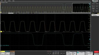
Below is the TX-D1 & CLK from the send side (when I issue IP pings)

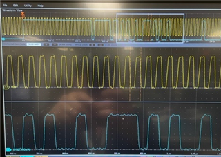
Below is a zoomed in view of the CLK and rising edge of TX_EN

I'm really at a loss here and could use some help.

  • Additional info.

    This is my interconnect board.  Pretty straight forward.  Even though it is physically very small (< 1' long), I ensured matched trace lengths and used 4 layer stackup to ensure trace impedance.  

  • Hi Phil,

    Unfortunately, E2E forums close automatically if there is no activity within the last month from the latest post. Since the last correspondence was 12-14-21, this is why it closed. Something I wanted to ask was if you are able to probe the clock signals at the EVM boards to ensure that they are at the correct amplitude. In addition, could you please send screen shots of the MAC signals on scope with measurements to confirm they are valid (see RMII slave TIMING section 6.6).

    Sincerely,

    Gerome

  • Gerome,

    I'm not in the office today but I can offer this info.

    The clock is 3V logic.  Screenshots showing the clock were right from XI pin(s).  I'm using this osc part to drive both board's OSC-IN.  

    https://www.crystek.com/crystal/spec-sheets/pro/CPRO33.pdf

    (osc circled in red)

    For the MAC signal timing validity, I tried to show that in the 3rd & 4th pics down from the top, in the first post.  When I get back to my bench, I'll try to get more/better captures.

  • Gerome,

    While I continue to overturn rocks, I ran across this old E2E thread.

    https://e2e.ti.com/support/interface-group/interface/f/interface-forum/675991/back-to-back-gigabit-ethernet-phys

    It talks about a similar application and the user is looking at using parts with RGMII interface.  Part of the response included mention of needing to shift the clock on one or both of the parts.  Does this have any applicability with my RMII application?  I see there is a setting at 0x17:8 for the clock in the DP83825i.  Thoughts?

  • Hi Phil,

    You can explore this with RMII, but I don't think it will be as applicable. While waiting for the scope shots, an idea with the team is to test out the other connection on the board to ensure that this is an MII issue. 

    1) Test out individually on each board. Put 825 into reverse loopback. This will create a signal path that goes:

    LP -> PHY -> LP (looping around)

    2) This will require both boards. 1 board will be acting normally while the other board will be in MII loopback. This will create a signal path:

    LP -> PHY1 -> PHY2 -> PHY1 -> LP

    The idea is to check the packets sent vs received to see if there is some corruption in the signal path.

    Sincerely,

    Gerome

  • Gerome,

    I plan to try the loopback(s) when I get back into the office on Monday (snow storm here now).

    Thanks,

  • Gerome,

    Here is a screenshot of RX_D1 and clock.  The RX_D0 looks the same.  This is the RX pins on the EVM connected to my PC and captured when I sent a series of pings.  There is nothing happening on the TX pins on this board (no data), which is the return path for the pings.  From what I can tell, the timing looks OK but I may be looking at it wrong.

    I am also working to figure out how to do a loopback test.  I don't currently have any tools on my PC to perform this test so I am investigating this.  If you have some ideas on what to use, it could help.  Someone suggested a tool called Wireshark.

    Phil

  • Hi Phil,

    I don't believe that Wireshark will work in this scenario. I am proposing to use either a packet generator software such as iperf, or use a third EVM to generate and check packets via MDI. Do you have a third board that can work in this scenario?

    In addition, when doing this ping, are you connecting the 10/100 board to the PHY or is the ping just from PC to PC?

    I will provide a diagram detailing the signal flow off of the loopback testing I am proposing. In the meanwhile, there is a reference design that utilizes the DP83825 PHY in a RMII repeater (with DP83822, but should be similar configuration): https://www.ti.com/tool/TIDA-010046

    Sincerely,

    Gerome

  • Gerome,

    I will likely need some more detailed help to try what you suggest with a third EVM.  I do have an extra board.  I suspect you are talking about putting the third board in some sort of test mode via register setting(s)?  Yes, a detailed diagram & instructions would help.

    I am familiar with the app note that you mentioned which connects a DP83825 with a DP83822.  I have a copy already and have looked at it several times.  I see nothing that I am doing different with the EVM board other than right now I am sourcing an external osc to two slaves whereas the appnote uses a master slave setup (which I tried first).  

    Here is a basic pictorial of setup.  When I say ping, I am sending pings to a 10/100 admin port on a server box which has a static IP.  If I bypass the whole EVM and connect the PC directly into the server, I works perfectly.  This is true no matter what speed I set the PC's NIC to (10 FD, 100 FD or autonegotiate).  When I put the EVMs in the middle and send pings, nothing is returned (".....destination host unreachable").  I see activity indicators flashing on everyone, When queried, I see EVM register responses that links are good on both sides but I only see RMII data activity in the direction from PC to server with no activity in the opposite direction. I have tried resetting each EVM after power up.  BTW......does the reset need to be absolutely simultaneous on both EVMs?

  • Hi Phil,

    Attached are the photos for the experiments proposed:

    Experiment 1: Reverse Loopback

    This is used to test out the MDI connections of both boards. 1 board will be used as a PRBS generator and checker (Reg 0x16[13:12] = '11'. This board will be connected to the other EVM via MDI. Board 2 will be in reverse loopback (Reg 0x16[4"0] = 0x10). The signal flow is as follows: PRBS generator generates the signal, goes to the other board, is loopback back via reverse loopback, and is checked with the internal checker to compare. 

    If everything goes fine, you should be able to read that we are locked and synced on received bit stream (Reg 0x16[11:10] = '10'), and there should be no BIST errors (Reg 0x1B[15:8] = 0). Please note that in order to clear the error count, you should write '1' to bit field [15]. 

    Experiment 2: MII Loopback

    This is an extension of the previous experiment, and while testing MDI connection of 1 board, also tests the RMII connection as well. If all goes well in experiment 1, this should in theory be able to isolate the RMII repeater connection. A third board is used as the generator and checker, which is connected to one of the boards via MDI. That board is then connected via RMII repeater to another board. That board is in MII loopback (Reg 0x0[14] = '1', and 0x16[2] = '1'). The third board's checker settings are similar to experiment 1. The intermediate board acts normally (no loopback). So the signal path goes from EVM3 (generator + checker) to EVM1 (via RJ-45) to EVM2 (via RMII), is looped back to EVM1 (via MII loopback), and is sent back across the RJ-45 to the checker.

    Experiment 3: EEE Possibility?

    Another working theory that came into mind is that one of the PHYs in the chain might be utilizing EEE, Energy Efficient Ethernet. This was brought about due to the comment that ping is only seeing activity in 1 direction. In the original configuration (PC - RMII Repeater - Server), can you please read the values of 0x4D1, 0x203C, and 0x203D on both PHYs? One or both of these PHYs might have been autonegotiated into EEE as this is a common feature in laptops. Specifically, I am looking at 0x4D1[0], 0x203C[1], and 0x203D[1]. Please note these are different MMID's, so extended register writes/reads might be needed. More information is located in section 7.3.11.1 in datasheet and examples of reads/writes are located in section 7.3.11.5 and .6.

    Sincerely,

    Gerome

  • Gerome,

    I will start work on these suggestions on Friday (1/28).  I am off site until then.

    Thanks!

    Phil

  • Hi Phil,

    Understood. Will await your response then.

    Sincerely,

    Gerome

  • Gerome,

    I tried looking at what you suggested above but was not successful mostly because the whole exercise was getting a bit unwieldy and I was having a hard time following the instructions for the EEE query (with the whole extended register access thing).  I am using the latest version of USB2MDIO GUI.  In the end, if the EEE thing was the solution, it looks like I might need an MCU to configure the chips on boot up, which is what I want to avoid.

    Anyway, in part because of the complexities involved in trying to get these eval boards to work, I have tentatively chosen to go down a different path.  Since the main interfacing function that I need is to convert a capacitively coupled 10/100Base-T interface to a magnetically coupled 10/100Base-T interface, I started looking as some small Ethernet switch ICs.  I couldn't find anything useful in TI's offerings so I went to a different mfr and found one that I was able to get working in one hour. This solution is much simpler to implement (single IC with single power rail) versus the DP83825i (x2), and it still serves my purpose.

    While I appreciate the help and perseverance with trying to resolve things, I really think that this problem with the EVMs was combination of my lack of experience with such devices and the not-so-great documentation associated with the chip and EVM (especially). 

    Regards,

    Phil