This thread has been locked.

If you have a related question, please click the "Ask a related question" button in the top right corner. The newly created question will be automatically linked to this question.

DP83867IR: Setting Test Mode for Compliance Test

Part Number: DP83867IR

Dear Madams and Sirs,

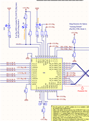
We are using two DP83867ISRGZR in Back-to-Back to create a 1000Mbit-Repeater. Because we have no MicroController on our PCB, we use the Strap Configuration as shown in the figure below.

Now we want to perform a compliance test. For this we need to activate the Test Modes on the Phys. This we want to do with an external MDIO-board and teh Putty terminal program. Actually we can read and write the registers. BUT, when we want to set one device in Test Mode 1 according to the App Note SNLA239B Page13, we get always the test signal sequence only on Channel A, independed on the Value of Register 0x25.

Do you have any idea, what is wrong in our setup? We want to see the test signal on every channel (A to D).

Thank you in advance.

Jens

  • Hi Jens,

    How are you writing to this register? If you read back that register, are you getting the values you previously wrote?

    Sincerely,

    Gerome

  • Hello Gerome,

    Thanks for your quick response.

    We tried reading the registers directly after writing and register 0x0025 did not accept the written value, it always stays 0000. Other register values were as expected.

    This was the sequence we followed.

    Reg 0x001F = 0x8000 //reset PHY
    Reg 0x0000 = 0x0140 //1000 Base-T Mode
    Reg 0x0010 = 0x5008 //forced MDI Mode
    Reg 0x0009 = 0x3B00 //Test Mode 1
    Reg 0x0025 = 0x0480 //output test mode to all channels
    Reg 0x01D5 = 0xF508

    Best regards

    Ana

  • Hello Gerome, Mrs. Jagar and her colleagues make the Compliance tests for us. Please feel free and communicate with them directly.

    Thank you in advance.

    Best regards,

    Jens

  • Hi Ana,

    What program are you using to program and access registers? Is it USB2MDIO, or another software? 

    Are you able to program registers within 0x0-0x1F and read back the appropriate value (i.e. 0x0 as that has many writable registers)? 

    It seems you are not utilizing extended register access. I would recommend utilizing this whenever writing to a register outside of [0x0, 0x1F]. Please see section 8.4.2.1 and 8.4.2.1.7 in the datasheet.

    Sincerely,
    Gerome

  • Hello Gerome,

    yes, we are using simple USB2MDIO connection.

    We followed the steps in the mentioned chapters and were then able to active test modes on all channels.

    Thank you for the hint!

    Regards

    Ana