Dear Madams and Sirs,
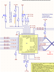
We are using two DP83867ISRGZR in Back-to-Back to create a 1000Mbit-Repeater. Because we have no MicroController on our PCB, we use the Strap Configuration as shown in the figure below.

Now we want to perform a compliance test. For this we need to activate the Test Modes on the Phys. This we want to do with an external MDIO-board and teh Putty terminal program. Actually we can read and write the registers. BUT, when we want to set one device in Test Mode 1 according to the App Note SNLA239B Page13, we get always the test signal sequence only on Channel A, independed on the Value of Register 0x25.
Do you have any idea, what is wrong in our setup? We want to see the test signal on every channel (A to D).
Thank you in advance.
Jens

