This thread has been locked.

If you have a related question, please click the "Ask a related question" button in the top right corner. The newly created question will be automatically linked to this question.

DP83867IR: Jitter test

Part Number: DP83867IR

Hi all,

My customer prepares two of the same boards on which the DP83867IRRGZ is mounted and connects them via a fixture to conduct a compliance test.
In the Jitter test, if the DUT can be linked with the link partner with the setting of Test Mode 2 or Test mode 3, will the LED of the DUT light up?
Registers related to LEDs such as LEDCR1 are left at their default settings.

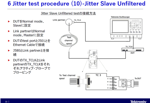
For example, in the case of "Jitter Master Unfiltered setting" in the explanation of Tektronix, DUT is set to Test mode 2, Link partner is set to Normal and Slave setting. Is there any problem with the following register settings?

Or does the Link partner set Test mode 3?

Master side (DUT):
1000 Base Test Mode 2 with TX_TCLK:
Reg 0x001F = 0x8000 // reset PHY
Reg 0x0000 = 0x0140 // 1000 Base-T Mode
Reg 0x0010 = 0x5008 // forced MDI Mode
Reg 0x0009 = 0x5B00 // Test Mode 2, Master
Reg 0x0025 = 0x0480 // output test mode to all channels
Reg 0x0170 = 0x81F // output clk a
Reg 0x00C6 = 0x0010 // proprietary

Slave side (link partner):
Reg 0x001F = 0x8000 // reset PHY
Reg 0x0000 = 0x0140 // 1000 Base-T Mode
Reg 0x0010 = 0x5008 // forced MDI Mode
Reg 0x0009 = 0x1300 // Normal, Slave


Regards,
Toshi

  • Hi Toshi,

    Your register setup is correct on the DUT side for the jitter compliance test. However, we do not need a link partner during  jitter test. Here is the figure below for the Jitter compliance test from IEEE 802.3:

    --

    Regards,

    Hillman Lin

  • Hi Hillman-san,

    Thank you for your reply.

    Sorry for the confusion. The Slave script is what I imagined and thought of. So it may be wrong.

    Regards,
    Toshi

  • Hi Hillman-san,

    As an additional confirmation,
    it is necessary to set each to Normal mode with TX‗TCLK output by Slave jitter test. Is the following setting correct?

    Master side:
    Reg 0x001F = 0x8000 //reset PHY
    Reg 0x0000 = 0x1140 //1000 Base-T Mode
    Reg 0x0010 = 0x5048 / Enable automatic crossover
    Reg 0x0009 = 0x1B00 //Normal mode, Master
    Reg 0x0025 = 0x0480 //output test mode to all channels
    Reg 0x0170 = 0x81F //output clk a
    Reg 0x00C6 = 0x0010 //proprietary

    Slave side:
    Reg 0x001F = 0x8000 //reset PHY
    Reg 0x0000 = 0x1140 //1000 Base-T Mode
    Reg 0x0010 = 0x5048 / Enable automatic crossover
    Reg 0x0009 = 0x1300 //Normal mode, Slave
    Reg 0x0025 = 0x0480 //output test mode to all channels
    Reg 0x0170 = 0x81F //output clk a
    Reg 0x00C6 = 0x0010 //proprietary

    DUT and Link partner were linked by Auto-negotiation.
    However, Jitter could not be measured because the TX_TCLKs of each other were not synchronized.
    It is confirmed that the clock signal of 125MHz is output from TX‗TCLK and the signal of 62.5MHz is output from MDI.

    Regards,
    Toshi

  • Hi Toshi,

    Can I have a block diagram on the jitter test you are currently working on? I am still not clear on why you need a link partner for jitter test?

    --

    Thank you,

    Hillman Lin

  • Hi Hillman-san,

    The following is the Jitter measurement procedure on the Slave side of Tektronix.
    Set both DUT and Link Partner to Normal mode.

    Please let me know if you have any other additional questions.

    Regards,
    Toshi

  • Hi Toshi,

    I will discuss this issue internally and provide you an response later this week.

    --

    Regards,

    Hillman Lin

  • Hi Hillman-san,
    Thanks for your support.

    I would like to report the following additional results and questions from our customers.

    ----------------------------------
    Regarding the clock synchronization at the time of Slave Jitter measurement, synchronization was achieved by setting according to the following procedure.

      Step 1. Set below and check the Master and Slave links.
          Master side:
           Reg 0x001F = 0x8000 // reset PHY
           Reg 0x0000 = 0x1140 // AUTO-NEGOTIATION ENABLE
           Reg 0x0010 = 0x5048 / Enable automatic crossover
           Reg 0x0009 = 0x1B00 // Normal mode,  Master
           Reg 0x0025 = 0x0480 // output test mode to all channels
           Reg 0x0170 = 0x81F // output clk a
           Reg 0x00C6 = 0x0010 // proprietary

         Slave side:
           Reg 0x001F = 0x8000 // reset PHY
           Reg 0x0000 = 0x1140 // AUTO-NEGOTIATION ENABLE
           Reg 0x0010 = 0x5048 / Enable automatic crossover
           Reg 0x0009 = 0x1300 // Normal mode, Slave
           Reg 0x0025 = 0x0480 // output test mode to all channels
           Reg 0x0170 = 0x81F // output clk a
           Reg 0x00C6 = 0x0010 // proprietary

    Step 2. Set Reg 0x00C6 on the Slave side to 0x0000.

    I have the following questions related to this.
    (1) Regarding Reg 0x00C6 [4], the corresponding bit is explained below, but it is not the clock of the received data from the Master side, but the CLK input from the crystal of the Slave PHY is simply multiplied by 5 and output. Is it a setting?

        ===Excerpt from the data sheet===============
        Internal Clock MUX Control:
        1 = Configures analog CLK_OUT to be TX_TCLK for compliance testing.
       =======================================

    (2) If the setting between DUT and the link partner is set to Reg 0x0000 = 0x0140 in the above settings, the link will not be established.
    Are there any other necessary settings or conditions?

    (3) The setting method is described in 2.2.5 Jitter Slave Unfiltered (Test Mode 2 and 3) of Application note (www.ti.com/.../snla239). It can be read that the Master side is set to Test mode 2 and the Slave side is set to Test mode 3, but how do you specifically use it?
    Even with this setting, they did not link to each other. Is the setting method different?

    -----------------
    Regards,
    Toshi

  • Hi Toshi,

    I discuss with the team internally on the jitter test. If you are doing a slave jitter test application, you only need to write the register on the slave side. You don't need to configure any register on the link partner or the master side.

    --

    Regards,

    Hillman Lin

  • Hi Hillman-san,

    Thanks for your response.

    As a confirmation, there is a function that can output TX_TCLK by Reg 0x00C6 [4] of DP83867. Is this correct?

    According to the attached Tektronix document, Test mode 3 needs to be set in Step 2 of "Jitter Slave Filterd" after P102 / 314, or Step 2 in the section of Jitter Slave Unfiltered.

    When measuring Jitter Slave of DP83867, which is recommended, whether TX_CLK is present or not?

    If TX_TCLK is enabled, please tell me the setting in normal mode for Master and Slave.

    TDSET3.pdf

    Regards,
    Toshi

  • Hi Toshi,

    Yes you are correct, 0x00C6[4] will enable the measurement for TX_TCLK through CLKOUT pin. Normal mode for Master and Slave should be the same. Changing register 0009 is the only requirement from switching master and slave mode.

    --

    Regards,

    Hillman Lin

  • Hi Hillman-san,
    Thanks for your answers.

    I asked the question on May 26th, but I will ask the same question again.

    Both Master and Slave are set with TX_TCLK output. What is the source clock of TX_TCLK on the Slave side after linking by Auto-negotiation?
    My understanding is that the source clock of TX_TCLK on the Slave side is based on the clock of the received data.

    When the customer confirmed, TX_TCLK of Master and TX_TCLK of Slave did not synchronize, so when they tried Reg 0x00C6 = 0x0000, Both TX_TCLKs  were synchronized.
    From this result, when Reg 0x00C6 = 0x0010, they think that the clock obtained by multiplying the frequency of Slave's XI by 5 is output.

    Please tell me what is really about this.
    Are there any mistakes or omissions in their settings?
    Do you have anything to check?

    Master side:
    Reg 0x001F = 0x8000 // reset PHY
    Reg 0x0000 = 0x1140 // AUTO-NEGOTIATION ENABLE
    Reg 0x0010 = 0x5048 / Enable automatic crossover
    Reg 0x0009 = 0x1B00 // Normal mode, Master
    Reg 0x0025 = 0x0480 // output test mode to all channels
    Reg 0x0170 = 0x81F // output clk a
    Reg 0x00C6 = 0x0010 // proprietary

    Slave side:
    Reg 0x001F = 0x8000 // reset PHY
    Reg 0x0000 = 0x1140 // AUTO-NEGOTIATION ENABLE
    Reg 0x0010 = 0x5048 / Enable automatic crossover
    Reg 0x0009 = 0x1300 // Normal mode, Slave
    Reg 0x0025 = 0x0480 // output test mode to all channels
    Reg 0x0170 = 0x81F // output clk a
    Reg 0x00C6 = 0x0010 // proprietary

    Thanks and regards,
    Toshi

  • Hi Toshi,

    Could you try with the script below when you are doing Jitter test for slave mode?

    Master:

    Reg 0x001F = 0x8000 // reset PHY

    Slave side:
    Reg 0x001F = 0x8000 // reset PHY
    Reg 0x0000 = 0x1140 // AUTO-NEGOTIATION ENABLE
    Reg 0x0010 = 0x5048 / Enable automatic crossover
    Reg 0x0009 = 0x1300 // Normal mode, Slave
    Reg 0x0025 = 0x0480 // output test mode to all channels
    Reg 0x0170 = 0x81F // output clk a
    Reg 0x00C6 = 0x0010 // proprietary

    --

    Regards,

    Hillman Lin

  • Hi Hillman-san,
    Thanks for your answers.

    Is DP83867 in master mode able to output TX_TCLK only by setting Reg 0x001F = 0x8000 // reset PHY?

    In the compliance test that the customer is trying to set, TX_TCLK is output from both the master and the slave, and the jitter of the slave TX_TCLK is measured based on the TX_TCLK on the master side.

    Regards,
    Toshi

  • Hi Toshi,

    I discuss this issue internally and we realized 867 does not support TX_TCLK for compliance test.

    --

    Sincerely,

    Hillman Lin

  • Hi Hillman-san,

    Thank you for your reply.

    As a final confirmation, does this conclusion mean that TX_TCLK cannot be used in all Jitter tests in compliance tests?
    Or does it mean that TX_TCLK in Normal mode cannot be used in the jitter test method that the customer was trying to do this time?

    Thanks and regards,
    Toshi

  • Hi Toshi,

    Yes, you are correct on the first statement TX_TCLK cannot be used in all the Jitter test in compliance tests.

    --

    Regards,
    Hillman Lin