This thread has been locked.

If you have a related question, please click the "Ask a related question" button in the top right corner. The newly created question will be automatically linked to this question.

TLK106: Some PHYs Fail to Boot at Temperatures above 50°C

Part Number: TLK106
Other Parts Discussed in Thread: DP83822H, DP83825I

Good Evening,

We are experiencing an issue with some TLK106 PHYs when powering up at elevated temperatures. We have multiple boards, each with 7 PHYs installed, and are seeing an average of 10-15% of the PHYs failing when powering up at 50C. The remaining 85-90% have no issues, even with power cycles up to 90C ambient. The problem PHYs will power up fine around 45C and will run properly up to at least 90C without any issues. But if we power cycle the board, the problem PHYs will fail to boot.

The symptoms seem very similar to https://e2e.ti.com/support/interface-group/interface/f/interface-forum/532984/tlk105-tlk106-in-ethercat-network-doesn-t-start-at-temperatures-over-35-c, but there are some notable differences in our design.

Design details:

  • 7 x TLK106 PHYs
  • MACs instantiated in Xilinx Zynq SOC
  • AVDD = VDD_IO = 3.3V
  • RMII mode
  • XI = 50MHz, 3.3V, generated from Zynq
  • Individual MDIO connections between each MAC and PHY

The 50MHz reference clock is generated by the Zynq programmable logic. The Zynq comes up less than 5ms after the PHYs are powered, but the loading/configuration of the programmable logic into the FPGA is taking upwards of 1700mS (yeah, 1.7 seconds). Consequently, the reference clock into XI is not stable until about 1.7 seconds after the PHY internal POR is de-asserted. We are holding \RESET low for another ~1.5 seconds after XI is stable while the linux operating system boots.

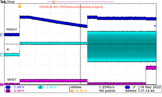
On the problem PHYs, we see the PFBOUT 1.55V supply start decaying linearly starting about 250ms after power-on. The slope of that linear decay appears to be directly related to ambient temperature; the higher the temperature, the steeper the slope. It appears that if PFBOUT only drops to 0.70V or so by the time that XI starts, PFBOUT will reset to 1.55V and the PHY will recover (see 1st scope shot). However, if the PFBOUT drops any further (either due to steeper temperature slope or further delayed XI start), PFBOUT will stay low and the PHY will be unresponsive (see 2nd scope shot). Notice the steeper slope.

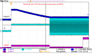
Once unresponsive, neither asserting \RESET or writing PFB_OFF via MDIO can revive the PHY (it appears the 1.55V powers the internal registers, so MDIO is dead).

On the working PHYs, we do not see any PFBOUT decay with power cycles up to 90C.

Questions:

  1. Is there a firm requirement for XI to be stable within Xms after/before AVDD power-up? I don't see any such timing requirement in the datasheet. Note: I was able to hack one PHY to delay AVDD, such that the clock was stable before power-up. With that hack, the problem PHY powered up perfectly.
  2. Is it known why this behavior is only present on some (10-15% of my sample size) PHYs? No correlation I can deduce from our boards; on one board, PHY1 and PHY7 are problematic, on another, PHY2 is problematic. It is seemingly random which PHYs will tolerate the condition. All PHYs in use are from the same lot/reel.
  3. Is there any workaround given the constraints of my design (XI comes 1.7sec after AVDD)? Asserting \RESET does not work.
  4. If this behavior is understood, is there a chance TI could screen the parts that will work in my application?

Thank you in advance for the help. Please forgive my less-than-perfect scope shots. The XI input is actually 0-3.3V, but given the challenge of scoping at 60C ambient in a small chamber, my lousy ground connection makes for an inaccurate voltage measurement of the 50MHz clock.

-Kyle, BSEE Avionics Design

  • Hi Kyle,

    Is this a new design? If so, we recommend using DP83822 or DP83826 PHY for you new design.

    If this is an old design, could you tell me anything change between the working system and newer system?

    --

    Regards,

    Hillman Lin

  • Hi Hillman,

    This is not a new design. We've had this design fielded for 4 years.

    No change between systems. The issue was only recently observed because we recently modified our test procedure to include power cycles during thermal cycling. Previous test procedures kept constant power to the board during thermal cycling. It is quite possible that we have numerous units in the field with this latent failure.

    I've been eyeing the DP83822H as a possible drop-in replacement. How confident are you that this problem wouldn't manifest with that part? Unfortunately, the DP83822H is seemingly unobtainable for several months, so I don't have the opportunity to test any.

    Thumbing through other TI datasheets this morning, I noticed a comment on the timing diagram in the DP83825I datasheet (sh11): "Clock shall be available at Power Ramp, Else additional RESET_N is needed". This seems to suggest that TI is well aware of part of the issue, and likely the TLK106 may be similarly affected. I'm hopeful TI has a workaround for use with my design.

    Thank you,
    Kyle

  • Hi Kyle,

    Could you reach out to FAE for design related questions on converting TLK106 to DP83822 in your design. There are also other options for 100Mbps for PHY which is recommended which is DP83826. Here is the information link for 826 PHY:https://www.ti.com/lit/ds/symlink/dp83826e.pdf?ts=1653071809338&ref_url=https%253A%252F%252Fwww.google.com%252F

    Meanwhile, we can ramp you up with 822 PHY.

    --

    Regards,

    Hillman Lin

  • Hillman,

    I appreciate your willingness to help ramp us up with the DP83822. Please let me know what the next steps are. That could prove to be a good solution for future builds.

    However, I still need guidance regarding the TLK106 for my numerous existing builds. Are you able to answer my original questions regarding the TLK106 behavior? It sounds like the answer to question #4 is a 'no'. Please help with my remaining questions:

    1. Is there a firm requirement for XI to be stable within Xms after/before AVDD power-up? I don't see any such timing requirement in the datasheet. Note: I was able to hack one PHY to delay AVDD, such that the clock was stable before power-up. With that hack, the problem PHY powered up perfectly.
    2. Is it known why this behavior is only present on some (10-15% of my sample size) PHYs? No correlation I can deduce from our boards; on one board, PHY1 and PHY7 are problematic, on another, PHY2 is problematic. It is seemingly random which PHYs will tolerate the condition. All PHYs in use are from the same lot/reel.
    3. Is there any workaround given the constraints of my design (XI comes 1.7sec after AVDD)? Asserting \RESET does not work.

    Thanks,
    Kyle

  • Hi Kyle,

    We don't have support on TLK106 right now. Sorry about that.

    --

    Sincerely,

    Hillman Lin

  • Hillman,

    Are you telling me that TI will not support me with my TLK106 design? Are we able to elevate this another way? Forgive my ignorance; this is my first experience with TI forum posts.

    Thank you,
    Kyle

  • Hi Kyle,

    I understand what you are saying, we really want to support you on this project. Unfortunately, TLK106 is NRND which is Not Recommended For New Design there is no support for this. In order to best support here we really recommend moving over to DP83822 board. 

    --

    Sincerely,

    Hillman Lin