This thread has been locked.
If you have a related question, please click the "Ask a related question" button in the top right corner. The newly created question will be automatically linked to this question.
I'm using I2C2 to communicate with TPS65987D (to flash microcode to its external spiflash) and I have some questions:
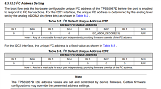
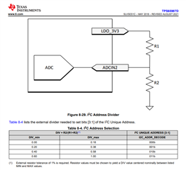
1. It seems I can't find the I2C address to start with.
2. slvae21a.pdf h has just some partial sample code that references a lot of #defines/info where details are missing. Where can I get the complete sample (esp the header files where register offset/bit/bytes meaning and data lengths of all sorts...etc)?
Thanks.
Hi James,
If you are using the flash, it might be address 0x50. Can you confirm which SPI Flash you are using or is this for EVM?
Unfortunately, I don't think we have the full code for this but I can confirm.
Thank you,
Hari
Hi James,
At the moment, I do not think we have the full code. I will need more time to check with our team.
For the flash, you will need to check the datasheet for that particular device for the I2C address as I am not familiar with this one.
Thank you,
Hari
There seem to be some confusion about I2C address here. The SPI flash doesn't need I2C address. The I2C address for the TPS65987D is defined based on resistor configuration of ADCIN pins. This is provided in TPS65987D datasheet.
Alright what I was experiencing is very strange:
My I2C communicates (wired) with TPS65987D over its I2C2 whose address is 0x70. However TPS65987D responds NAK. BUT, if I use the I2C1 address (0x40) , then TPS65987D responds to I2C2 lines. I feel the documentation could be mistaken between I2C1 and I2C2 for the address?
Again, please help provide the full example as I mentioned above. The source sample in slvae21 is only the .c part of it. Without full sample code, it's unusable.
Thanks.
Hi James,
The I2C address should be according to the documentation as they are set and controlled by the default device firmware, I'll double check and confirm with you by tomorrow.
The example in the document should be treated as sudo code. On page 6, there is a flash update execution flow chart that demonstrates the logic behind flash update over I2C. The technical reference manual (TPS987D TRM) includes all the information for 4CC commands as shown in the flow chart. We do not have a full code as that's dependent on the EC connected to the PD controller.
Regards,
Raymond Lin
Hi Raymond, did you have a chance to verify why the I2C addresses are cross-referenced as I observed?
Hi James,
The hardware ADCIN pin-strapping (the ADCINx divider) can override the firmware so please verify your voltage divider matches the decode when you set it up (as shown below on page 41 of the datasheet)
If your current I2C setup works as intended, then it should be fine to keep it as is.
Regards,
Raymond Lin
Hi Raymond, thanks for your quick response. Above is my actual hw setup for ADCIN1 & ADCIN2 address selectors (both grounded). However, I2C2 responds to address 0x40 before loading its microcode (blank flash). And after the microcode is loaded, I2C2 then responds to address 0x70. I'm OK with this with some unnecessary extra FW logic though. However, it is very important to me to understand this behavior; especially why the address switches AFTER microcode is loaded...etc. I'd appreciate it if you could help clear this confusion. Thanks.
Hi James,
I'm not too sure why the I2C addresses are reacting like that. Let me consult with a firmware team member and get back to you by Thursday, thank you for your patience.
Regards,
Raymond Lin