This thread has been locked.

If you have a related question, please click the "Ask a related question" button in the top right corner. The newly created question will be automatically linked to this question.

DS110DF410: Max insertion loss that DS110DF410 can support

Part Number: DS110DF410
Other Parts Discussed in Thread: DS250DF410

Hi Expert,

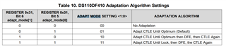
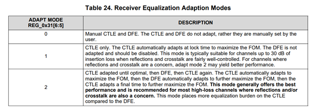
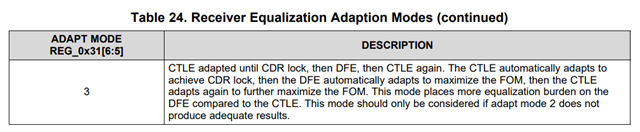
How to set the CTLE, DFE  with insertion loss, for example, what is the max insertion loss which DS110DF410 can support?

Thanks

Best regards,

David

  • Hi David,

    The DS110DF410 is able to apply up to 34 dB of boost at 5 GHz in order to compensate for insertion loss.  In a high loss situation, you can leverage the device's "Adapt Mode 2", which automatically adapts CTLE and DFE when locking to the signal.

    Thanks,
    Drew

  • Hi Drew,

    Thanks for your feedback.

    34dB @ 5GHz is only CTLE or CTLE+DFE?

    What is the max boost can CTLE support? how many stages CTLE?

    For the "Adapt mode ", find below table in the datasheet, 

    what is the difference of the 4 adapt modes

    Under what condition use one of each adapt mode and how to use

    What is the total boost of each adapt mode?

    Best regards,

    David

  • Hi David,

    I would count on the 34 dB of equalization including DFE.

    I don't have an exact number for the max boost provided by just CTLE, but typically DFE provides +/- 3dB of equalization at most.  Based on this, you can anticipate around 30 dB of equalization from CTLE at 5 GHz.  The CTLE has 4 stages.

    Regarding the differences between different adapt modes, please find an excerpt from our 10G retimer programming guide below.

    https://www.ti.com/lit/an/snla323/snla323.pdf

    Thanks,
    Drew

  • Hi Drew,

    Thanks for you feedback.

    "typically DFE provides +/- 3dB of equalization at most" , this is for the DFE of TI part, or it is the common level across the semiconductor?

    If can increase from +/- 3dB to +/- 5dB or whatever more by increasing the taps number, for example from 2 taps to 5 taps or 8taps?

    For the 4 stages of CTLE, how to connect the n stage and n+1 stage because need to eliminate the DC common voltage?

    For the total 34 dB of equalization, how to determine the channel insertion loss, can we use the chip in a channel interstion loss of 50dB?

    What is the max criteria of the channel insertion loss?

    Thanks

    Best regards,

    David


  • Hi David,

    The first tap is primarily responsible for compensating for insertion loss.  Additional taps are responsible for correcting for ISI, crosstalk, and reflections.  Because of this, just adding taps does not allow for additional compensation.  In general, the majority of the insertion loss in a system should be equalized through CTLE.

    The CTLE stages are connected internally, so there is not a need to worry about the DC common mode voltage between stages.  You will need AC coupling capacitors on the high speed I/O of this device.

    I would recommend simulating the device with the intended channel.  I don't have an exact maximum insertion loss that the device supports since this will depend on the characteristics of the channel, but I would expect it to be around the 34 dB of equalization that the device can provide.

    Thanks,
    Drew

  • Hi Drew,

    Thanks for your feedback. Understand the reason why increasing taps can not make much difference for the compensation.

    The questions is that, if first tap is for the compensation for the insertion loss, and additional taps for the ISI, cross-talk and reflections.  

    What is the use of increase 3 Taps to 5 taps?

    Yes, will do simulation for the device with intended channel, what kind of simulation tools do you recommend for the simulation?

    Thanks

    Best regards,

    David

  • Hi David,

    Typically we use Keysight ADS for IBIS-AMI simulations.

    Regarding the number of DFE taps, using less taps reduces power consumption and reduces adaptation time.  Using more taps can be advantageous when equalizing less ideal transmission channels such as passive copper cable.

    Thanks,
    Drew

  • Hi Drew,

    Thanks for your feedback. Could you help give some example of passive copper cable?

    What about the absolute mW of percentage of power consumption and  adaptation time increase with  taps number increase?

    Thanks

    Best regards,

    David

  • Hi David,

    An example of passive copper cable is a passive SFP / QSFP cable.

    Please see power consumption from DS250DF410 datasheet.

    Unfortunately, I don't have any measurements on how much adaptation time increases.

    Thanks,
    Drew

  • Hi Drew,

    Thanks for your feedback.

    • #1 Based on 1st and 2nd row of the table, the crosspoint part account for 8mW because the total power increase from 233 to 241.
    • #2 DFE taps 3-5 account for 13mW because the total power increase from 220 to 233
    • #3 DFE taps 1-2 and DFE taps 3-5 account for 30mW because the total power increase from 211 to 241

    Based on above #2 and #3, the DFE taps 1-2 account for 17 mW.

    Is my understanding correct?

    If correct, why the DFE taps 1-2 consume more than DFE taps 3-5, two taps consume 17mW and 8.5mW per tap.

    DFE taps 3-5 consume 13mw, 3-tps consume 13mw and 4.3mw per tap.

    Could you help explain why the tap power consumption is not equal distribution over the taps?

    Thanks

    Best regards,

    David

  • Hi David,

    I'm not familiar with the exact considerations that go into this device's design and how those impact power, but I would hypothesize that there is some inherent power consumption increase that occurs simply by enabling DFE.  Based on this hypothesis, I would break down DFE power as follows: 30mW = 4.3mW / tap * 5 taps + 8.5mW DFE system power.

    Is this small variation in power consumption critical to your design?

    Thanks,

    Drew

  • Hi Drew,

    Thanks for your detail feedback. Does the 4.3mW / tap and 8.5mW DFE system power related to the process, for example, if porting to advanced process, 4.3mW / tap and 8.5mW DFE system power  will decrease?

    Best regards,

    David

  • Hi David,

    Unfortunately I do not have the analog design knowledge that would be required to answer this question.

    Thanks,

    Drew

  • Hi Drew,

    Thanks a lot a understanding. Don't have any further questions about this topic.

    BTW, do you know how to delete the thread when the problem solved?

    Best regards,

    David

  • Hi David,

    We typically do not delete threads in order to have them for future reference.

    Thanks,
    Drew