Other Parts Discussed in Thread: DS250DF410
Hi Expert,
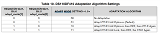
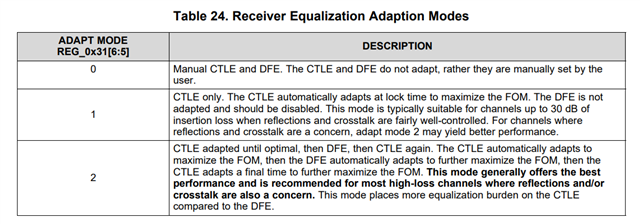
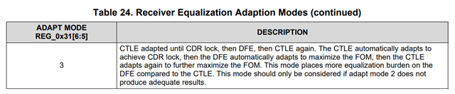
How to set the CTLE, DFE with insertion loss, for example, what is the max insertion loss which DS110DF410 can support?
Thanks
Best regards,
David
Hi Expert,
How to set the CTLE, DFE with insertion loss, for example, what is the max insertion loss which DS110DF410 can support?
Thanks
Best regards,
David