This thread has been locked.

If you have a related question, please click the "Ask a related question" button in the top right corner. The newly created question will be automatically linked to this question.

TUSB217A-Q1: AC boost, ISI compensation and cable length support

Part Number: TUSB217A-Q1
Other Parts Discussed in Thread: TUSB216I, TUSB217-Q1

Hi team,

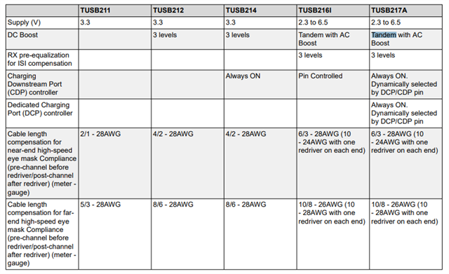
I have couple of questions on TUSB21x family, i looked through the e2e history question but no clear answer:

1. RX pre-equalization for ISI compensation: can you give an example of the problem that TUSB216I/7 could solve but TUS211/2/4 can't? Is RX pre-equalization equal to AC boost?

2. Can you explain more about the last two column? 

  • USB2.0 is bidirectional protocol and TUSB21x should compensate for either direction (correct me if i am wrong), why does the pre-channel and post-channel spec make sense?
  • Why far-end cable length is much higher than near end?

3. Customer need to use 5.4m usb cable to connect two ECU (saying headunit and rear seat usb box), could you provide the recommend solution? There are two option in consideration, 1 TUSB21x in the mid of cable (with a bridge board), or two TUSB21x at both end of the ECU.

Regards

Dongbao

  • Hi Dongbao, 

    1. RX pre-equalization is not equal to AC Boost, it is just compensation for ISI Jitter, and can be chosen at 3 levels depending on how much loss may be being caused by ISI jitter. Other older redrivers do not compensate nearly as much for this loss, so later redrivers such as the TUSB217-Q1 are good choices to help fix this.

    2.A, Yes, redrivers are bidirectional, meaning they can receive a signal coming from either direction and inject current into said signal. Pre-channel talks about how much distance you can have before a signal needs a redriver to boost the signal, and post-channel describes the distance the signal should still be compliant within after going through the redriver. More info can be found here: https://e2e.ti.com/support/interface-group/interface/f/interface-forum/719929/faq-when-implementing-a-usb-3-x-signal-redriver-what-is-the-difference-between-pre-channel-loss-and-post-channel-loss .

    2.B, Far-end cables usually mean the redriver is placed at the target device rather than the host, so there is generally more distance that is covered before the redriver is implemented to the greatest effect.

    3. For that length, I believe it would be best to implement 2 redrivers, one directly in the middle of the cable, and another at the end of the cable. This could change after testing though. If you have any schematics in mind, feel free to send them and I can give them a look.

    Let me know if you have any other questions or need some clarification.

    Thanks,

    Ryan

  • Hi Ryan,

    Thanks for your reply.

    I am still confused about Q2 and Q3

    1. Is the signal compensation direction independent? If so, what make the difference of redriver placement? It could be used in any location between host and slave. Also, the pre-ch and post-ch spec doesn’t make sense any more.

    2. For 5.4m cable support, do you have any concern on adding two connectors that bring additional resistance discontinue? According to the table, two redirves on each end should support 10m cable, is that true?

    Dongbao

  • Hi Ryan

    Do you have any feedback? thanks

  • Hi Dongbao, sorry for the late reply,

    1. If I am understanding what you are asking, yes, signal compensation direction is independent. The main thing with redriver placement is that you will want to use it either at the connector of the host or device, and then in the middle of the cable if the cable goes longer than the recommended distance without a redriver, I.E 5M. The pre-channel loss spec mainly identifies the amount of loss the redriver can compensate for in the distance between say a host and a redriver. The post-channel spec describes the amount of loss present after passing through the redriver. One of the redrivers main goals is to compensate for all the pre-channel loss and some of the post-channel loss so that the signal can go a farther distance.

    2. For a 5.4M cable, 2 redrivers should be able to compensate for any resistance discontinuities that occur with placing the redrivers in the path. As for placement, you can cover up to 10M with 2 Redrivers, the key thing is placement. In the case of a 10M cable, you would place one at the beginning of a signal, at the host, and place another at the midway point, approximately 5M away from the previous redriver. You could also potentially have on redriver on each end. This thread talks about distance and placement of multiple redrivers in a path: https://e2e.ti.com/support/interface-group/interface/f/interface-forum/873193/tusb213-about-serial-connect-for-10m-cable

    Please let me know if you have any other questions or need some clarification.

    Thanks,

    Ryan