This thread has been locked.

If you have a related question, please click the "Ask a related question" button in the top right corner. The newly created question will be automatically linked to this question.

DS110DF410: Support In Debug and configuring the DS110DF410SQ IC

Part Number: DS110DF410

Hi Team, 

We are using DS110DF410SQ IC in our design and we are not getting the video output as expected ( we are using it for ARINC 818 video stream)

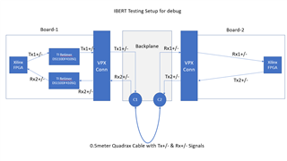
I have attached the overall setup and how we are debugging this, and we have few observation related to this debug

We have Xilinx FPGA in the board and since we were not able to get the required video we are into debug mode and xilinx support IBERT were we can run the random PRBS patter to see the behavior of the signal Transmission and reception in the FPGA
So here we observe
Observation 1:
when Both Tx1 to Rx 1 path and Tx2 to Rx2 path is enabled ( PRBS data transmission) board 1 & 2 observe the errors at the respective Rx
Observation 2:
When Tx1 to Rx 1 path is disable ( no PRBS data transmission) then the board 1 (Rx2) will receive the data properly without any issue

we are still debugging and would get input from TI what might be the issue and how can we fine tune this with retimer configuration

Note :
we have total 8-Tx & Rx channels and we see this issue only in two channels
Seperate Retimers for Tx and Rx is used

Regards,
Karthik

  • Hi Karthik,

    The following information would help TI to debug:

    • Data rate and PRBS pattern being used
    • Retimer input and output channel s-parameters, if available
    • What are the settings being used for the transmitter to the retimer Rx in question: voltage amplitude differential, pre-cursor and post-cursor de-emphasis?
    • Does the system board have AC coupling capacitors for both the retimer high-speed inputs and outputs?
    • Can you provide a full retimer channel registers dump for both a failure case and a good case?

    Thanks,

    Rodrigo Natal

  • Hi Rodrigo Natal,

    • Data rate and PRBS pattern being used
    • <iW>: PRBS 31 @ 1.0625Gbps Data rate
    • Retimer input and output channel s-parameters, if available
    • <iW>:This is not availble
    • What are the settings being used for the transmitter to the retimer Rx in question: voltage amplitude differential, pre-cursor and post-cursor de-emphasis?
    • <iW>Default setting
    • Does the system board have AC coupling capacitors for both the retimer high-speed inputs and outputs?
    • <iW>: Yes, there we have 220nF AC caps retimer input and output as recommended in the datasheet
    • Can you provide a full retimer channel registers dump for both a failure case and a good case?
    • <iW> This currently is not availble, i will try to get this asap
    • Basic Configuration 0xFF = 0x0C // Change control from Control Reg Set to Channel Reg Set,
    • 0x00 [3:0] = 4'h0 // Reset all Channel Registers (RST_REGS)
    • 0x36 [5:4] = 2'b11 // Enable the 25 MHz reference clock .
    • 0x2F = 8'h66 // Rate & SubRate Settings
    • 0x60 = 8'h80 // PPM count Settings
    • 0x61 = 8'hAA // PPM count Settings
    • 0x62 = 8'h80 // PPM count Settings
    • 0x63 = 8'hAA // PPM count Settings
    • 0x64 = 8'hFF // PPM Tolerance Settings
    • 0x0A [3:2] = 2'b11 // Reset CDR
    • 0x0A [3:2] = 2'b00 // Pull Out of CDR Reset

    Regards,

    Karthik

  • Try the following channel registers setting adjustments:

    • 0x2F -> leave this register at its default value
    • 0x18 
      • Set bits 6:4 to b011 to force "divide by 8" setting
    • 0x09 -> set 0x09[2]=1 to enable the divide select override
    • 0x0C -> set 0x0C[3]=0 to disable the Single Bit Transition check function

    Regarding: Can you provide a full retimer channel registers dump for both a failure case and a good case? This currently is not availble, i will try to get this asap

    • If you still run into rttimer issue after using my register setting recommendations then do provide the requested retimer channel registers system log values

    Thanks,

    Rodrigo Natal