This thread has been locked.

If you have a related question, please click the "Ask a related question" button in the top right corner. The newly created question will be automatically linked to this question.

DP83822I: Unable to connect normally

Part Number: DP83822I
Other Parts Discussed in Thread: DP83822EVM, DP83869HM

Hi

The customer has an EtherCAT product, the structure is the EtherCAT Slave IC connected to the DP83822i through the MII interface, and the DP83822i was set to the optical fiber mode through the hardware Strap setting, and the connection can be normally connected through the optical fiber;

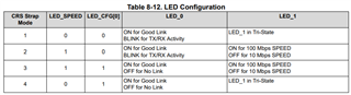
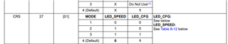
However, due to the flexibility of the design, it is necessary to test to set the DP83822i to the copper cable mode, and then connect the fiber module SPS-3120G through RXD_N, RXD_P, TXD_N, TXD_P. Please refer to page 4 of the attached file for the connection method. , Read Bit 14 of 0x000A Control Register #2 (CR2) to confirm that it has switched to copper mode, and the fiber module SPS-3120G also confirms that it can be connected to the fiber hub (the FP LED of the fiber hub is on), the DP83822i’s The CRS STRAP Mode is Mode 4, but the LED_0 maintains the level of about 3V, and the TXD_N and TXD_P do not send any signals. Is there any possible reason why the DP83822i cannot be connected normally?

SPS-3120G.pdf

  • Hi Gareth,

    Just to be sure I'm following correctly:

    -Device is Strapped to be in MII mode and communicate through Fiber.

    -Device must be switched to copper mode

    -Bit 14 of 0x000A confirms copper mode

    - CRS STRAP Mode 4 LED_0 ON confirms there is still link

    Check Bit 14 of Table 8-43 0x001F PHY Reset. 

    This will reset the phy without clearing the registers. 

    Regards,

    Alvaro

  • Hi Alvaro

    The customer modified the components on the DP83822 EVM board according to the suggested wiring diagram of SPS-3120G. Although the signal is unstable, the optical fiber connection Media Converter has been able to connect with other EtherCAT devices, but now encounter a strange problem, when COL Strap When Mode is 2, DP83822 is preset to fiber mode, and the result of reading 0x000A Control Register #2 of DP83822 is also 0x4100, However, the voltage of LED_0 has been maintained at high level (3V). Instead, when the Strap Mode of COL is changed to 1, and then 0x4100 is written to 0x000A Control Register #2, the level of LED_0 will change from high to low. The condition of the module has always been normal, and the FP Link/ACT lights of the Media Converter are all on. What is the reason that LED_0 keeps at a high level in fiber mode?

  • Hi Gareth,

    Do you know what LED_0 functionality you are using? Below is a screenshot of the different configurations for LED_0. It can be controlled by the LED_SPEED and LED_CFG bits, which are controlled by the strapping of the CRS pin (also screenshotted below). Both Screenshots came from Section 8.5 in the Datasheet.

    Could you also check Register 0x0001 Basic Mode Status Register bit 2 for link status

    Regards,

    Alvaro

  • Hi  Alvaro

    R53 and R55 on DP83822EVM are not loaded, so CRS Strap Mode is 4, R84 is 13K ohm, R88 is 1.96K ohm, COL Strap Mode is 2, the result of reading 0x0001 BMSR is 0x7849, but with the fiber The FP Link/ACT of the Media Converter connected to the module is lit;

  • Hi Gareth,

    CRS Mode 4 means LED_0 is ON for Good Link and OFF for no link.

    COL Mode 2 means device has 100BASE-FX enabled.

    The reading of 0x0001: 0x7849; means that there is no link.

    But you're saying that the FP Link/ACT of the Media Converter is saying there is link?

    In Fiber mode, use the Signal Detect Pin (LED1). See Section 8.4.4.2 in DS for more details. This can be enabled by setting RX_ER to Mode 3 or 4 ('4' is Default).

    Are you able to link up in fiber initially? Is the problem when you switch to Copper?

    As to why LED_0 is changing when switching from Fiber to Copper, I will need to consult a team member for that one.

    Regards,

    Alvaro

  • Hi Alvaro

    Later, it was found that the polarity of LED_GPIO (LOS) was reversed. The default of DP83822 is Active HIGH, and SPS-3120G is Active LOW. Later, by writing 0xff01 to 0x0465 (FIBER GENCFG) to change the polarity of Signal Detect, LED_0 becomes Good Link, Is there any way to set the Signal Detect polarity through hardware Strap?

    Although the connection can be made at present, there is still a problem in the part where the fiber optic module is connected to the Media Converter. The Media Converter we use is SKC-1211 SC/MM/02. When the fiber optic module continues to send packets, the TP of SKC-1211 The flickering frequency of Link/ACT is significantly lower than that of FP Link/ACT. It seems that the SKC-1211 will not transmit the packets to the RJ45 interface every time after receiving the packets through the optical fiber. Is there any recommended optical fiber switch or conversion module that can be used? What about the test on DP83822? Or this phenomenon has nothing to do with SKC-1211?

  • Hi Gareth,

    Alvaro is on PTO until next Monday. I can help you in the meantime.

    There is no strap to change the polarity if Signal Detect. You can disable the signal detect through strap if the application is okay with it.

    We don't have any recommendation on the optical media converters. However, you can used our device DP83869HM for fiber media converter applications.

    Please let me know if you need more details.

    --
    Regards,
    Gokul.