Because of the Thanksgiving holiday in the U.S., TI E2E™ design support forum responses may be delayed from November 25 through December 2. Thank you for your patience.

This thread has been locked.

If you have a related question, please click the "Ask a related question" button in the top right corner. The newly created question will be automatically linked to this question.

DP83867IR: SGMII ethernet link inconsistency issue faced when using TI DP83867IR phy with Xilinx Zynq Ultrascale+ RFSOC

Part Number: DP83867IR
Other Parts Discussed in Thread: DP83867IS, TXS0102

Hi,

We are facing SGMII ethernet link inconsistency issue when using TI DP83867IR phy with Xilinx Zynq Ultrascale+ RFSOC.

On Phy side we have configured “SGMII Enable=1 (Mode 2), and RX_CTRL=0 (mode 3).”

Prior to ethernet link going down we get below error message in the Petalinux  log.

[  401.013577] TI DP83867 ff0b0000.ethernet-ffffffff:00: Master/Slave resolution failed

  1. Can you please advise based on what condition the above error message will be reported from the driver?
  2. Has anyone else faced this error?

Regards
Louis

  • Hi Louis,

    Are you able to provide more detail for when link inconsistency or drop occurs? Please also send a register dump from addresses 0 to 1E to confirm PHY strap configuration.

    When the problem occurs, please attempt writing 4000 to 1F on the PHY to see if link comes up.

    Thanks,

    Evan

  • Hi,

    We found there is intermittent MDIO access failure on the boards where the ethernet link inconsistency is seen. We suspect that the intermittent MDIO access failure is causing the ethernet link to go down.

    First we are trying to understand cause of the MDIO access failures.

    We repeatedly read the PHYID1 (address 0x2) and PHYID2 (address 0x3) registers and captured the MDIO waveform in passing and failing case.

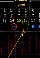
    In the fail case, TI phy device seems to have started driving seems to have started driving the Read register value one clock cycle early resulting in FPGA latching the data incorrectly.

    See attached slides (Slide 4 and 5 for waveforms comparing Passing and Failing case0

    I have two queries:

    1. Please advise if you have some input on reason for the Phy device driving the MDIO bus one clock cycle early on read?
    2. What is the Delay specification for Phy device to start driving the MDIO bus between 15th and 16th Clock cycle of MDIO register read access? [ We need this data to verify that the RFSOC device MDIO set time requirement of 80ns before the MDC clock rising edge is met]

    MDIOinterfaceAccessIssueDebug_0.2.pdf

  • Hi Louis,

    Is there any other PHY also connected on MDC/MDIO of the FPGA?

    If another PHY is connected, can you power down this PHY while observing MDIO signals?

    Please specify what link inconsistency refers to - is link periodically returning, or staying down?

    Thanks,

    Evan

  • Hi Evan,

    The DP83867IS is the only Phy device connected on the MDC/MDIO of the FPGA.

    The inconsistency is as below:

    1. On multiple MDIO read access, (Reading PHYID1 and PHYID2 registers) on some iterations, we get invalid response. On probing the MDIO signal in fail case, we find that Phy device starts sending Read register response one clock cycle early compared to Table 3 and Figure 17 of the DP83867 datasheet.

    See my attachment slide 4 and 5.

    2. Ethernet link inconsistency: Once it goes down it does not recovery by itself. We suspect that this is due to MDIO access failures.

  • Hi Louis,

    MDIO read failure should not be the root cause of link failure/inconsistency. It is possible that link is still good, but MDIO read failure prevents you from reading the status of the PHY properly.

    Are you able to verify that link is failing using a method aside from MDIO reads? This could be through LEDS_0/1/2, or through probing the input/output data between two link partners.

    [  401.013577] TI DP83867 ff0b0000.ethernet-ffffffff:00: Master/Slave resolution failed

    My current assumption is that the issue is on the MDIO side, as this log is dependent on MDIO reads.

    Thank you,

    Evan

  • Hi Evan,

    I agree, I think link is good. We verified that SGMII eye mask requirement is met. However, because of MDIO access issues, I suspect the linux device driver is disabling the SGMII interface on the Xilinx RFSOC.

    I would like to understand the reason for the MDIO access failure:

    1. Please advise if you have some input on reasons for the Phy device driving the MDIO bus one clock cycle early on read?
    2. What is the Delay specification for Phy device to start driving the MDIO bus between 15th and 16th Clock cycle of MDIO register read access? [ We need this data to verify that the RFSOC device MDIO set time requirement of 80ns before the MDC clock rising edge is met]

    Thanks

    Louis

  • Hi Louis,

    Please advise if you have some input on reasons for the Phy device driving the MDIO bus one clock cycle early on read?

    There may be some skew on the MDC/MDIO lines, but more information is needed to confirm this. Are you able to decrease the MDC frequency and see if this behavior changes?

    What is the Delay specification for Phy device to start driving the MDIO bus between 15th and 16th Clock cycle of MDIO register read access?

    The standard defines a 2-bit time spacing delay as the turn-around time, relative to the MDC.

    Referencing slide 4 - on the 14th clock cycle of the failing case, the issue could be on the MAC end with the ZU67 releasing the last register address bit one clock cycle early.

    Thank you,

    Evan

  • Thanks for your response Evan.

    1.  Try with Decrease of MDC clock frequency:

    Current MDC clock frequency setting is 2.08MHz.

    We tried reducing the clock frequency to 1.5625Mhz and 1.04MHz and the MDIO access issue was not seen in 5 iterations

    However at 446KHz and 781KHz, the MDIO access failures were seen.

    With 1.5625Mhz MDIO frequency, the ethernet ping was not working. We are checking with Xilinx if any other setting is required to make ping work after changing the MDC clock frequency.

    2. Can it specified - After the 14th MDC clock rising edge of a MDIO read access, how much minimum and maximum delay will the DP83867 Phy device start driving the MDIO line?

    Referencing slide 4 - on the 14th clock cycle of the failing case, on 14th clock rising edge the MDIO line is high. Shortly after the rising edge the MDIO line goes low. My understanding is that if the ZU67 had released the MDIO line early, the MDIO line would have remained high, not gone Low.

    3. Please note as share in the slide (slide 3), we have TI TXS0102 device on the MDIO/MDC interface between ZU67 and DP83867 phy

    We included this device to keep the external MDIO interface in tristate before the Test board (with phy device) is plugged in and to enable it by software control.

    This TXS0102 device includes One Shot rising-edge rate accelerator circuitry.

    We suspect if this device is contributing to this issue. 

    Please let us know if you have any information on possibility of the TXS0102 device causing problems on this interface.

  • Hi Louis,

    We typically don't see active components on the MDC/MDIO lines - is the TXS0102 necessary for this application?

    The MAC and PHY in this case both follow the MDC/MDIO standard set by 802.3 - we do not expect any issues if the application doesn't deviate from the standard and datasheet recommendations.

    Please check if the failing case can be reproduced while shorting across TXS0102. 

    2. Can it specified - After the 14th MDC clock rising edge of a MDIO read access, how much minimum and maximum delay will the DP83867 Phy device start driving the MDIO line?

    I am in the process of looking for this information, please expect a follow-up on this by Wednesday 11/30 due to holiday.

    Thank you,

    Evan

  • Thanks Evan.

    I will wait for the turn around time specifications.

    Regarding TXS0102:

     We included this device to keep the external MDIO interface in tristate before the Test board (on which Phy is present) is plugged in and to enable external MDIO interface by software control. 

    We tested shorting across the TXS0102.

    With the default MDC clock frequency of 2.08Mhz, we observed fail in 3 out 11 MDC read access iteration (One read iteration includes 1000 read of PHYID1 and PHYID2 registers)

    We reduced MDC clock frequency to 1.04MHz and passed in all 10 iterations.

    We reduced MDC clock frequency to 781KHz and passed in all 10 iterations.

    When we reduced MDC clock frequency to 446KHz, MDIO read access failed in 2 out 6 iterations.

    Is there a minimum MDC clock frequency which the Phy supports.

    Next we are testing with reduced MDC frequency without shorting TXS0102 and will update.


    Regards
    Louis

  • Hi Louis,

    I am not able to specify the turnaround time beyond what is quantified in the standard - 2-bit time spacing. In the case of running MDC at 2.08MHz, the maximum turn-around time is then 0.96 us.

    Are the MDIO/MDC signals being measured on the test board or radio board end? If measured on the radio end, please repeat the tests on the PHY end instead.

    Is there a minimum MDC clock frequency which the Phy supports.

    I do not think so, although I will confirm with the team and get back to you on this.

    Thanks,

    Evan

  • Thanks Evan.

    From the IEEE Std 802.3-2018, section 22.3.4 MDIO timing relationship to MDC it is specified

    "When the STA sources the MDIO signal, the STA shall provide a minimum of 10 ns of setup time and a minimum of 10 ns of hold time referenced to the rising edge of MDC,as shown in Figure 22–18, measured at the MII connector."

    "The clock to output delay from the PHY, as measured at the MII connector, shall be a minimum of 0 ns, and a maximum of 300 ns"

    With respect to turnaround time behavior and considering the timing specifications in the IEEE standard:

    At the 14th MDC clock rising edge, the STA (ZU67) drives last register address bit for minimum of 10ns after the MDC rising edge and then tristates the MDIO line.

    Till 15th MDC clock rising edge both STA (ZU67) and Phy device tristate the MDIO line.

    After 15th clock rising edge, the Phy device will drive the MDIO bus with 0 with minimum delay of 0ns and maximum delay of 300ns.

    However, in the fail case as can be seen in the slide 4 and 5 of the document I attached, the Phy device seems to have started driving 0 after the 14th MDC clock rising edge (instead of after the 15th MDC clock rising edge)

    As mentioned in previous update, we are seeing significant improvement when we bypass the TXS0102 device.

    Could the TXS0102 device be contributing to this issue and causing the Phy to start sending MDIO read data 1 clock cycle early?

  • Hi Louis,

    It is possible that the TXS0102 is introducing some delay/distortion/... to the signal path that causes this behavior, but I am unfamiliar with this device and use-case so I cannot provide a precise recommendation.

    Are the MDC/MDIO signals being measured from the radio board or test board side? 

    Thanks,

    Evan

  • Hi Evan,

    The earlier captures shared were captured at the Radio board.

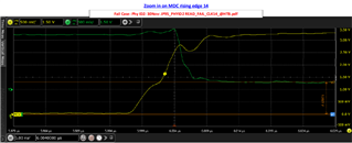
    We have today captured waveform at the Phy end (both passing and Failing case). We have also zoomed in on the clock at the 14th and 15th MDC clock cycles. Please review and let us know if you see any issues/ any cause for the Phy starting to drive read response one clock early in fail case.

    Please find attached the captures. 

    (Louis Dec 2: Updated file with additional details and  uploaded )

    MDIOinterfaceAccessIssueDebug_CaptureatPhyEnd_0.3.pdf

    Also we had earlier included a 100pF capacitor at the TXS0102 MDC output to improve signal integrity.

    We tested by removing the TXS0102 device along with 100pF capacitor and shorting the MDC signal across the TXS102 pads. Similarly shorted MDIO signal across the TXS0102 pad.

    With this we were not able to reproduce the MDIO access and Ping inconsistency issue.

    Can someone from TI with expertise on the TXS0102 (Clemens Ladisch?) also comment on possible reason for TXS0102 contributing to the unexpected behavior of the DP83867 Phy starting to drive read response one clock early in fail case?

    Thanks

    Louis

  • Hi Louis,

    Please create a new thread to receive assistance for the TXS0102, using this existing thread as context. 

    Thank you,

    Evan

  • Sure Evan. 

    I will create a new thread for TXS0102.

    • From DP83867 side, based on the MDIO/ MDC waveforms shared at Phy end, is it possible to explain any reason why the PHY device is driving the MDIO line one clock cycle earlier than expected in the fail case?

    From the MDC/ MDIO waveforms, the setup/ hold timing requirement of 10ns/10ns at PHY end are met. So I am not able to understand why the PHY device is driving the MDIO line one clock cycle earlier than expected in the fail case.

    2671.MDIOinterfaceAccessIssueDebug_CaptureatPhyEnd_0.3.pdf

    I have one more observation to share:

    As shared in the HW interfacing diagram on slide 2, we have a 100pF capacitor on the MDC signal at the TXS0102 output to reduce overshoot on the MDC signal at PHY end. [The waveforms shared above are taken with this configuration]

    For testing purpose, we tested by retaining the TXS0102 and only removing the 100pF capacitor. In this case the MDIO access passed (Tested for 15000 read accesses of PHYID1 and PHYID2). Also tested across temperature from -50C to +65C.

    With the 100pF capacitor present, as can be seen from the shared waveforms, we are not violating the PHY device MDIO setup/ hold timing specification of 10ns/10ns.

    • Please advise if you have some explanation why the presence of the 100pF capacitor on the MDC signal at TXS0102 output seems to be causing the PHY device to drive the MDIO line one clock cycle earlier than expected in the fail case?

    Thanks

    Louis

    Note: For reference: I have created below ticket on the TXS0102 related query:

    TXS0102: Issue observed on MDIO interface between Xilinx Zynq Ultrascale+ and TI DP83867 PHY with TI TXS0102 device in between - Logic forum - Logic - TI E2E support forums

  • Hi Louis,

    Is the error reproducible if removing the 100pF capacitor and TXS0102?

    Please advise if you have some explanation why the presence of the 100pF capacitor on the MDC signal at TXS0102 output seems to be causing the PHY device to drive the MDIO line one clock cycle earlier than expected in the fail case?

    I cannot comment on the behavior of the TXS0102 output paired with a capacitor. As you have shown that the capacitor on its own does not cause the PHY to violate setup/hold time, I would suspect the behavior is caused by the TXS0102. 

    Thank you,

    Evan 

  • Hi Evan,

    From the shared MDC/MDIO waveforms at Phy end, is it possible to give explanation of why the PHY device is driving the MDIO line one clock cycle earlier than expected, during the turnaround time, in the fail case?

    Is any specification of the Phy device getting violated which could cause this behavior?

    I am following up on this to make sure we understand the root cause of this as we get into volume production.

    Thanks

    Louis

  • Hi Louis,

    Looking at the zoomed in data/clock waveform for the 14th rising edge of the failing case, it appears the minimum hold time of 10ns is being violated relative to the voltage level of the MDIO signal.

    Operating on the 3.3VDDIO domain, VIH > 1.7V, and VIL < 0.7V. The MDIO signal in the waveform settles on ~1.5V after the clock edge, so it is unclear if it is being registered as a logic high or low for the clock cycle. As it stays at this voltage for the full clock cycle, its unknown logic state is likely violating the hold time.

    Thank you,

    Evan

  • Hi Evan,

    In Failing case immediately after 14th MDC Clock cycle rising edge and next falling edge MDIO is at 1.5V indicating contention on the MDIO
    signal.

    The ZU67 actively drives the MDIO line with 1 at the falling edge before 14th MDC clock cycle rising edge till the next falling edge after 14th MDC clock cycle.

    The Phy seems to have started driving the MDIO line with 0 at the 14th clock cycle rising edge resulting in contention on the MDIO line.

    The apparent hold violation appears to be because the Phy has unexpectedly started driving its response 1 clock cycle early as can also be seen as by the remaining bits driven on 15th and subsequent clock cycles which are all driven one clock cycle earlier than expected.

    Is any specification of the Phy device getting violated which could cause the Phy to start driving the MDIO bus one clock cycle earlier than expected?

    Thanks

    Louis

  • Hi Louis,

    The Phy seems to have started driving the MDIO line with 0 at the 14th clock cycle rising edge resulting in contention on the MDIO line.

    I am unsure if the ~1.5V level is caused by contention between the SOC & PHY, or if it is caused by the output behavior of the TXS0102.

    Is any specification of the Phy device getting violated which could cause the Phy to start driving the MDIO bus one clock cycle earlier than expected?

    The PHY should not be driving the MDIO line one cycle early, as the MDC/MDIO waveforms prior to the 14th clock cycle are all within the setup/hold time specifications. 

    Thanks,

    Evan

  • Hi Evan,

    We observe the MDIO voltage at 1.5V, immediately after 14th MDC Clock cycle rising edge and till next falling edge, on both sides of the TXS0102 (Phy end and FPGA end) which seems to indicate that the TXS0102 is fully ON.

    Based on above observation I think it is unlikely that the TXS0102 output behavior is the cause of the 1.5V on the MDIO line.

    Anyhow based on our testing so far, after removing the 100pF capacitor, which was placed close to the TXS01012 MDC output, we do not see the MDIO access failures.

    Also, we tested placing 100pF capacitor on MDC close to the Phy end (no capacitor close to the TXS0102 MDC output) and with this configuration also we do not see the MDIO access failures.

    We will keep this under observation for a couple of weeks and if no issues observed, will conclude with this solution.

    Thanks

    Louis