This thread has been locked.

If you have a related question, please click the "Ask a related question" button in the top right corner. The newly created question will be automatically linked to this question.

TIC12400: query

Part Number: TIC12400

    Need technical expert recommendation from about TIC12400 for following queries.


  1. Can we read the analog voltage of all input through SPI?
  2. If yes, then can you provide the mode recommendation if I want to read the multiple analog input?
  3. Can we use partial channels as sensor analog interface and some channels are switch input?
  • Prahlad,

    An engineer has been notified of your questions and will respond by end of business CST 02/01/2023.

    Regards,

    Eric Hackett

  • Hi Prahlad,

    Yes, the 10-bit digital codes from the ADC can be read directly through SPI for each Input Pin through the ANA_STAT0 through ANA_STAT12 registers (address range 6h to 16h).

    The analog voltage can then be calculated by:

    (ADC digital code x Reference Voltage) / (Number of Digital Output Codes) = Calculated voltage

    For example, Digital Code 0x155 (341 decimal) would correspond to the following analog voltage:

    (341 * 6) / 1023 = 2V

    Each Input pin can be individually configured to use either the ADC or Comparator and each Input pin can be individually enabled or disabled.  This allows you to use some or all of the Input pins in which every mode you would like. 

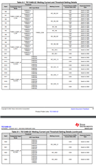
    However, there are some wetting current and threshold settings that are shared between some of the pins that you may want to consider when making your pin assignments.  The datasheet contains a table that shows all possible common settings that are shared between multiple input pins. 

    If you are only using the Input pin to monitor an external voltage with the ADC, such as the voltage from a sensor,  then a wetting current value of 0-mA is commonly used with that type of configuration.  An input pin that shares a wetting current with the Analog Input pin that needs 0-mA of wetting current, could not be configured to have a different wetting current value to be used with a switch. 

    For example, IN0 and IN1 would be required to share a common wetting current value, but inputs IN2 and IN3 can have different wetting current values than inputs IN0 and IN1.

    Regards,

    Jonathan