This thread has been locked.

If you have a related question, please click the "Ask a related question" button in the top right corner. The newly created question will be automatically linked to this question.

THVD1449V: IEC61000-4-5 Protection, Selectable Termination, and Bandwidth

Part Number: THVD1449V
Other Parts Discussed in Thread: THVD1454, THVD1424, TVS1401

Hi

We've got an upcoming RS485 Design. Our requirements for this interface are:

  • 500Kbps RS485
  • Half Duplex
  • IEC61000-4-5 Level 2 (8/20us test: 1KV / 42 ohms)
  • Selectable 120 ohm termination
  • Not isolated

We are considering using THVD1449V for this, but I have some questions:

  • I am concerned that this is a 12Mbps transceiver, and we want to use it on a 500Kbps bus. I worry about sharp edges, reflections, and radiated EMI. Others have suggested adding some series resistors to limit this, but I think this is not a great solution, as we don't know what other devices will be on the bus and I worry about what will happen as the bus capacitance loading gets high. Am I right to be worried about the fast slew rate, or is it pretty common to see 12Mbps transceivers on 500Kbps busses?
  • I plan to add an opto relay to control the selectable termination. Similar to what's suggested for CAN in TIDA-01238. However, I really do not like this solution for a number of reasons. Lifetime of the TLP175A opto is a concern, max 50 ohm RDSon. Etc. I think I can find a better opto for it, but is there a better solution that would not have these issues? I'd rather find like an analog switch with huge input voltage range. 
  • If I do add an external switch, can I rely on the Vclamp chart in the THVD1449V to protect it?  I don't see typical TVS ratings listed in that datasheet to know what the max Vclamp is, but I do see some sort of typical chart in figure 8-8. Can I assume that the VClamp for about 25A is around 30V?

The other approach I have considered is to use THVD1454, which has the selectable termination integrated and a slew rate limit. Questions with this approach:

  • This part is in preview. When will it be available to order for production?
  • I would add separate external surge protection TCLAMP1202P for this via TVS diodes. The VClamp will be about 15-20V. But the absolute max for THVD1454 is -16 to 16V. So it's close, but realistically I think there will be a short period of overvoltage, and I'm not sure if the THVD1454 will tolerate it. Any way to know this?
  • This approach would parallel the existing TVS protection on the THVS1454 with the new TVS protection. Should I be concerned about this? How do I ensure that the surge doesn't destroy the THVS1454 internal ESD protection?

  • Hi,

    Thanks for reaching out!

    1. So you can run a 12Mbps device on a 500kbps - but there are a few considerations

    1a) Running the THVD1449V at 500kbps will work just fine and it should be able to communicate on the bus. Most of the frequency content is still going to be centered around the data-rate, but since the edge rate is faster there is more higher frequency energy generated when using a faster device. So that means that impedance mismatch in the system will create high frequency reflections as well as lower frequency ones. Even in a well designed system there will be some impedance mismatch due to tolerance of the components on the bus - so if the system is sensitive to EMI or you are trying to design to hit specific EMC requirements usually a faster device isn't ideal. I

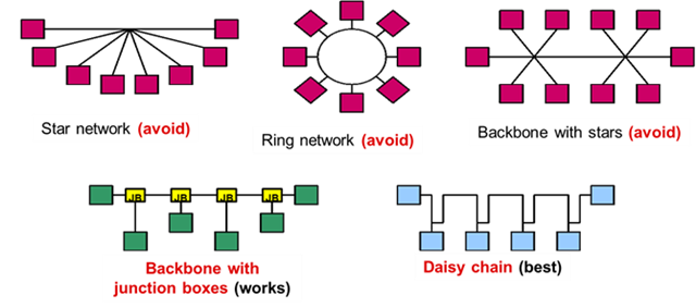
    1b) If the bus is properly terminated you should be able to get similar distances - but with a significant caveat: max stub length will be reduced. In a proper RS-485 system with more than 2 communication nodes it is preferred that the nodes follow the following topology guidelines:

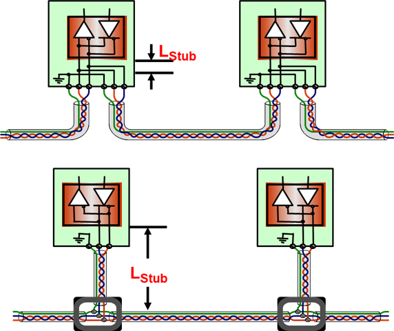
    Where Star and Ring networks generally make communication near impossible due interference created by the bus - while there are ways to implement those networks the design efforts to make them work well is generally not advantageous. The two suggested topologies are shown below with the stub length highlighted - all non terminal nodes (so every node except each end node) is not terminated and is connected to the main bus via a stub.

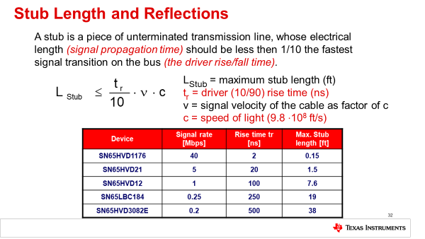
    This Stub length has a max length before it must be considered a parallel transmission line to the load transmission line - which means these are potential points of reflection are created. 

    The max length of the stub is dictated by the following process:

    So it really depends on the system parameters if the higher speed part will be okay - if the nodes are daisy chained together - very little risk, but otherwise it could be a potential problem. 

    2. Using an opto relay to control termination is possible - and the CAN reference design is the same one we have pointed to in the past when wanting selectable termination when it isn't integrated into the device for RS-485 so the suggestion is the same. I would advise against a switch - most analog switches that have large voltage ranges are going to require large voltage supplies handle the large input voltages - and many analog signal switches are limited in how much current they can channel through them - a power switch may work - but even then I think it may be a bit overkill and the voltage supply requirements usually are a big reason you don't see switches on the RS-485 bus directly - I think the opto relay is a better option from a design point of view 

    3. So the device will clamp the node - but the current will be shunted through the switch into the integrated surge protection of the IC - and it could be a lot of current that I would worry would fry the switch during a surge event. The THVD1449V would most likely be okay but the switch would be prone to damage. Just as some background - I worked on analog switches before I covered these parts and its very hard to implement switches on a RS-485 bus - not that you strictly can't but usually its very disadvantageous from a system design point of view. I understand the opto-relay isn't the must attractive option but I do think it is the more tried and true method of having non-integrated selectable termination. 

    So with all this considered I'd say the THVD1449V with an opto-relay is most likely the best option if implementing this device. If the stub lengths aren't too long  and the topology is favorable then I think its a decent choice moving forward.

    Now for your questions on the THVD1454.

    1. It should tentatively, as this could change, release in Q2 2023 - that's all I can really share - but we do have EVM's available if you want to start testing earlier. That also being said we have a device in the same family - the THVD1424 which is released that can be configured as a half or full duplex device through the H/F pin - they are very similar in performance and both have the integrated termination and the slew rate control pin (SLR).

    2. A lower clamping diode would be needed - beyond +/-16V could potentially fry the device.

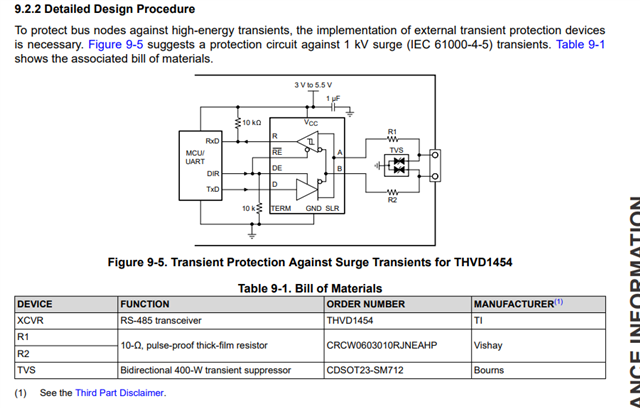
    3. Please see recommended setup for 1kV surges for the THVD1454 (its the same situation on most RS-485 devices)

    So both parts are possible and have the potential to work - the THVD1424 is also available now and can be configured as a half duplex device through the H/F pin.

    Please let me know if you have any other questions - either of these solutions are possible but they both have their tradeoffs.

    Best,

    Parker Dodson

  • Hi Parker, 

    Thanks so much for the really detailed answer on this. I'm leaning toward the THVD1454 based on that recommendation shared in the datasheet section 9.2.2. That circuit sure does look like it checks all of the boxes for us, and it avoids the opto. 

    But I have a few concerns about this. 

    Some specs for CDSOT23-SM712 are as follows:

    • IPP = 17A
    • Peak power = 400W, derate above 25C
    • Vclamp @17A = -14V, +26V.

    So, my concerns are:

    • The peak current in IEC61000-4-5 level 2 test will be 1KV / 42 ohm = 24A. But this diode is rated for 17A. 
    • Power derating means that at 85C, the peak current is just 11.05A. 
    • The clamp voltage is 26V, which is higher than the 16V abs max rating of THVD1454.

    I feel like I am overthinking this, but I did also see  some of the same questions and concerns from another poster in this thread: THVD1510: Surge transients protection IEC 61000-4-5. I don't really want to use TVS1401 due to the slew rate limit. 

    I have seen other suggestions to add thyristors and TBUs, but I would prefer not to do this if it isn't necessary.

    Ben

  • Hi Ben,

    So I understand your concerns - and I agree - you may need a more robust diode - but slew rate limits could be an issue with more robust devices. Generally speaking a device that will have a similar working voltage but with a higher current allowance (without the max clamping voltage exceeding the ratings of the suggested diode).

    I don't have any other diode suggestions directly, but I am going to loop in a protection expert into the thread that will be able to offer better guidance and may have a better idea of suggested solutions. 

    Best,

    Parker Dodson

  • Hi Parker, 

    I found a TVS that seems suitable, but it is a bit pricey. Semtech TCLAMP1202P. According to their datasheet I would need 3 of these guys. I'm not sure this is any better than using the thyristor + TBU + TVS approach that I see everywhere.

    • Ipp = 100A
    • Cj = 12pF
    • Vclamp @12A = 25V, @100A = 40V. 

    I considered TVS1401. Our slew rate at 500Kbps using THVD1454 will be 1.5V / 200ns (from the datasheet) = 7.5V/us. The TVS1401 max slew rate at 85C is 1V/us. So it won't work, unfortunately.

    One other thing I noticed that I had missed before is that there are 10 ohm resistors in series with THVD1454 outputs in that surge schematic. Those might actually mitigate some of the concerns about paralleling the TVS protection. I feel that solution might be okay.

    And I guess for I will share an observation about the 17A rating for CDSOT23-SM712. Basically, 17A is the average of the current amplitude during the 20us surge. Even though the peak current is 24A, that doesn't last for 20us. I guess this makes me feel a bit better about using the CDSOT23-SM712.

    Ben

  • Sorry for dragging this out, but I would also like to ask how those 10 ohm series resistors would impact the 120 ohm termination. Seems like with those in the circuit, it would now be 140 ohms. Should I be concerned about the SI?

  • Those resistors are commonly used to reduce the current through the internal protection diodes. RS-485-compliant transmitters have enough drive strength to handle the additional load (the driver can generate about 2 V over a 54 Ω load; the receiver needs only 200 mV).

  • Hi Clemens,

    I agree that the 10 ohm resistors will help mitigate the surge. I'm more concerned that by adding 2x10 ohm resistors in series, now the 120 ohm termination becomes 140 ohms. I am not sure if I should worry about that or if 140 ohm termination is okay. 

    Ben

  • They are small enough so that they do not have much of an effect on impedance matching.

  • Hi bbcuf,

    As you've found the TVS1401 won't work here due to the slew rate limitation, that would be our only option around 14 V that can dissipate a 1kV surge with a 42 Ohm network. The TCLAMP device will work here. 

    The +/- 16 V absolute max ratings of the transceiver are DC ratings, ESD/Surge are transient events so the transceiver may be able to handle slightly higher voltages. 

    The 10 Ohm resistors will limit the current at the input of the transceiver helping to protect the internal ESD protection. As Clemens mentioned the resistors are small enough so they shouldn't have much of an effect on impedance matching. 

    And I guess for I will share an observation about the 17A rating for CDSOT23-SM712. Basically, 17A is the average of the current amplitude during the 20us surge. Even though the peak current is 24A, that doesn't last for 20us. I guess this makes me feel a bit better about using the CDSOT23-SM712.

    The 17 A rating for the CDSOT23-SM712 is the peak pulse current rating for the 8/20uS waveform, not an average of the current amplitude. If an 8/20uS surge was injected with a higher peak current than 17 A the diode would likely fail. 

    Regards,

    Sebastian