This thread has been locked.

If you have a related question, please click the "Ask a related question" button in the top right corner. The newly created question will be automatically linked to this question.

THVD1500: Output current limit the drive capability

Part Number: THVD1500

Hi Team,

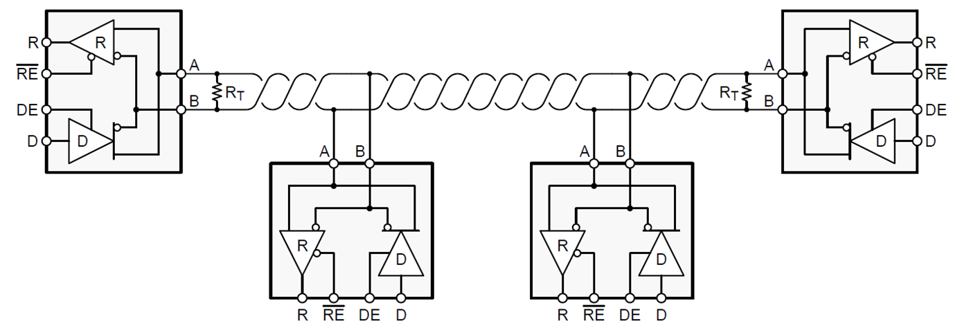
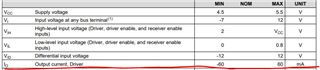
My customer is facing a problem when using THVD1500. They set the RL=120ohm and found that the output current, driver allows only 60mA. They think the drive capability is a little low when they are adding more than6  THVD1500 on the same bus.  (6x120ohm in parallel is 20ohm, 20ohm*60mA=1.2V on the Bus) I am not sure if it is really the gap of drive capability of THVD1500 or the understanding of customer is wrong on this case?

If the it is the drive capability issue of THVD1500, do we have some coming devices with higher driver output current?

If it is the misunderstanding or there are some methods to improve based on customer's situation, could you pls give us some explanation and insight on this?

Thanks for your support!

  • An RS-485 bus should have exactly two termination resistors, one at each end. This is independent from the number or placement of transceivers. (The termination must be at the end of the cable even if there is no transceiver at this end.) See the RS-485 Design Guide.

  • Hi Manu,

    Clemens is correct - in an RS-485 bus there are exactly two termination resistors, one at each end of the bus. The minimum impedance that should be seen between A and B during normal operation is 54 Ohms - or 2 120 Ohms in parallel with up to +/-10% tolerance (so 60 Ohms +/-10% has a minimum value of 54 Ohms).

    For unterminated nodes there are a couple considerations that need to be included in the design process. 

    1st Consideration: Bus Topology

    Ideally you want to use Daisy Chain for the network topology as this topology has the best performance with respect to signal integrity of the system. 

    Backbone with junction boxes also is acceptable but it can create its own issues as it generally will have a longer unterminated stub length.

    Using Star, Ring, Backbone with stars, or other non-ideal topologies will greatly degrade signal integrity. This is largely due to the signal reflections that will be present in these system topologies which will greatly decrease the performance of the signals.

    The 2nd Consideration is unterminated stub length. Essentially the termination resistors are there to mitigate reflections - it is assumed that the cabling/traces between nodes has a characteristic impedance of 120 Ohms (ideally 120 Ohm twisted pair wiring would be used between nodes). Unterminated stubs can start to reflect if they become to long relative the data signals transition time on the bus. 

    Where stub length is measured for the spine with junction boxes (bottom) and daisy chained (top) systems is shown below:

    To calculate the max stub length for unterminated nodes you follow the following equation:

    Where tr is the differential rise or fall time. v is the phase velocity of the transmission medium expressed as a percent (its value is between 0 and 1) and c is the speed of light. 

    For the THVD1500 the minimum differential transition time is 180ns.- so tr for this device is 180ns 

    v is going to depend on the specific cabling/traces used - but a v value of 70% is a pretty common one.

    c is the speed of light

    L <= 180ns/10 * 0.7 * c 

    Max L ~ 3.777m

    So if the unterminated stubs are less than 3.777m the reflections caused by the stubs should be negligible assuming v = 0.7 for your specific system. 

    So in conclusion:

    1. RS-485 has exactly 2 termination resistors - one at each end of the bus - equal to 120 Ohms.

    2. Other Nodes are unterminated.

    3. In Multi-point RS-485 systems daisy chain or spine with junction boxes are the preferred topology methods - as other will causes SI issues.

    4. Unterminated Nodes are connected to the main bus via an unterminated stub. This stub could reflect incident signals if it is too long. For this device assuming a signal propagation of 70% the speed of light this is about 3.7m for this part - so you can have longer stubs due to the parts lower rated speed. 

    Please let me know if you have any other questions!

    Best,

    Parker Dodson

  • Hi Parker,

    Great thanks for your detailed answer,  so from your opinion, the parameter drive output current will not be a problem when driving multi-nodes in daisy chain topology, and maximum 60mA should be ok. Am I understanding it correctly?

    So could you pls help to explain a bit more about the parameter "output current, driver", on which function may this parameters have impact, that would help me to have a better understanding on this case, thanks!

    Regards,

    Manu 

  • HI Manu,

    1. Yes the output drive capacity shouldn't really be an issue if the system is in a daisy chain topology, only the 2 terminal nodes (each end of bus) are terminated, and as long as there are no more than 256 Communication nodes on the bus communication should be possible with the expected drive current.

    2. Output current is based on a few factors:

    2a) First you need to consider termination between A and B - as this will determine a lot of the current. For this device we typically see 2V between A and B. 2V/54Ohms ~ 37mA under typical conditions. 

    2b) Common mode loading - the other communication nodes on the bus also load the system, and the driver will also send current to their loads as well. Each THVD1500 has a minimum impedance of 96K (it is a 1/8th unit load device - so 96K is the minimum - as 256 nodes in parallel is 375 Ohms - which is the minimum common mode impedance to ground. So the voltage at the "A" / input impedance of all of the transceivers on the line will also draw some current - this amount will be small until you have many nodes on the line.  A similar analysis is found on "B". The common mode voltage output is typically 2.5V  and a differntial output voltage of  2V - gives a typical "A" voltage of 3.5V and "B" voltage of 1.5V. So if you have a fully loaded bus (375 Common mode loading) the additional current would be 3.5/375 = 9.3mA and for the "B" node  1.5/375 = 4mA.

    2c) Differential capacitance - the capacitance between A and B will also shunt current - but for this device the bus needs to be pretty long before a lot of current is shunted through bus capacitance as this device is pretty slow which allows for large capacitances before significant current is lost through it. 

    So under a typical fully loaded bus you are probably only requesting  37mA + 9.3mA + 4mA ~ 50.3mA total with a full loaded bus at typical operating conditions. So the rec. +/-60mA still gives some margin from a fully loaded typical bus. So the 60mA really should be fine for most applications

    Please let me know if you have any other questions!

    Best,

    Parker Dodson