This thread has been locked.

If you have a related question, please click the "Ask a related question" button in the top right corner. The newly created question will be automatically linked to this question.

DS90C387: Signal Timing Inaccurate - Causing monitor to enter Diagnostics Mode

Part Number: DS90C387
Other Parts Discussed in Thread: TFP401

Hello,

Im developing a HDMI to LVDS bridge using TFP401APZP with DS90C387VJDX/NOPB - This is a dual channel converter.

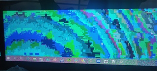
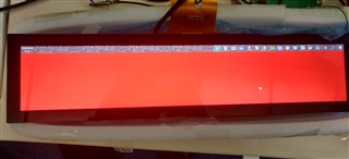
I am experiencing an issue with the display entering Diagnostics mode (Alternating between full red, green, blue, black, white) when I connect a HDMI cable to the board).

I have tested all combinations of the configuration pins (BAL, DUAL, PD, R_FDE, R_FB, etc.) and nothing causes any improvement. Each of these combinations were also tested with all relevant combinations of control pins in TFP401APZP (results attached in spreadsheet, and none caused the screen to be displayed).

In the past i experienced issues with EDID and HDCP - The EDID has now been corrected and the EDID was copied from the driver board provided with the TFT. I am using a raspberry Pi 4 as a HDMI source, eliminating the need for HDCP. Therefore i doubt these are the source of the issue, but there could be something I'm missing of course.

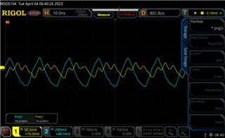
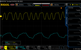
I have measured the ELV3_P, ELV3_N and ELVCLK_P,ELVCLK_N differential waveforms with an oscilloscope and there is a clear difference between the working driver board (75MHz each), and my board(25MHz and 60MHz)

Could you please provide some insight as to what else could be causing the screen to boot into Diagnostics mode, as there is clearly a signal being supplied and all the possible combinations of control pins have been tested.

Best Regards,

Kacper

Working AD Board (Yellow = EVEN Data 3, Blue = EVEN CLK):

My Design not working as expected (Yellow = EVEN Data 3, Blue = EVEN CLK):

Schematic:

8117.Schematic.pdfP19 TFT.pdf

  • Hello,

    I wasnt able to attach the Input Control Testing.

    If you would want to see this, could i please attach it in an email.

    Best Regards,

    Kacper

  • Hi Kacper, 

    Thanks for your question. How has this been narrowed down to the DS90C387 specifically? Can you isolate each device and probe each state to understand if issue is coming from TFP401 (DVI to parallel) or DS90C387 (parallel to OLDI).

    Can you try monitoring the signals out of the TFP401 to see if those are incorrect? If so, you will need to make an another thread for that device so it is appropriately mapped to the part owners of that device in TI. 

    Regards, 

    Logan

  • Hi Logan,

    Thank you for your response.

    The signals coming from the TFP401 look okay. I have now managed to get an image displayed, however it is distorted and i would really appreciate your help with identifying what could be causing the issue.

    What we are receiving now is this image:

    As you can see its the desktop, however the colours are distorted. I am unsure if this is caused by using the wrong number of RGB bits (48 instead of 36, could you confirm this from the attached TFT datasheet please?)

    When the desktop colour is set to a solid blue (0,0,255), solid green(0,255,0) or solid red(255,0,0) then the colour appears okay (red shown below for reference)

    However when i set a combination of colours, for example orange(255,140,0), the screen still apears red:

    Can you please, please help with deducing what could be causing the issue.

    I have attached the EDID we are using below, alongside the TFT Datasheet.

    The settings for the TFP401 are:

    OCK_INV = 3V3

    DFO = GND

    PD = 3V3

    ST = 3V3

    PIXS = 3V3

    STAG = 3V3

    PDO = 3V3

    We have changed these multiple times and the issue cannot be resolved by us, could you please please help us.

    The control pins on the DS90C387 are:

    BAL = GND (we have tried to change, but board stops working)

    DUAL = 3V3 (we have changed this to 1.65V and the board stopped displaying)

    PD = 3V3

    R_FDE = 3V3

    R_FB = 3V3

    We have also tried to change the Pixel Clock from 108MHz(Dual Channel) to 150MHz (Dual channel) but the issue remains the same.

    We have also tried to change so single pixel-dual pixel mode, but the display stops working then, we therefore think that it should be in 48-bit dual pixel mode for the 2 channels to work.

    I have attached the EDID and datasheet. Could you please, please, please guide us as to what could be wrong.

    We have tried everything we can think of and are desperate for some help, we would really appreciate it.

    Working EDID.txt
    00 FF FF FF FF FF FF 00 
    1D 85 01 24 01 00 00 00 
    20 12 01 04 A1 2B 1B 6D 
    EF C5 C6 A3 57 4A 9C 23 
    12 4F 54 00 00 00 01 00 
    01 00 01 00 01 00 01 00 
    01 00 01 01 01 01 30 2A 
    80 18 71 68 8E 11 12 20 
    0A 08 40 6C 20 00 00 3E 
    00 00 00 FF 00 35 31 36 
    38 0A 20 20 20 20 20 20 
    20 20 00 00 00 FA 00 09 
    4F 01 00 01 00 01 00 01 
    00 01 00 0A 00 00 00 FC 
    00 4C 43 44 20 4D 4F 4E 
    49 54 4F 52 20 20 01 29 
    02 01 04 00 02 3A 80 18 
    71 38 2D 40 58 2C 45 00 
    D7 40 32 00 00 1E 01 1D 
    00 72 51 D0 1E 20 6E 28 
    55 00 D7 40 32 00 00 1E 
    01 1D 80 18 71 1C 16 20 
    58 2C 25 00 D7 40 32 00 
    00 9E 00 00 00 00 00 00 
    00 00 00 00 00 00 00 00 
    00 00 00 00 00 00 00 00 
    00 00 00 00 00 00 00 00 
    00 00 00 00 00 00 00 00 
    00 00 00 00 00 00 00 00 
    00 00 00 00 00 00 00 00 
    00 00 00 00 00 00 00 00 
    00 00 00 00 00 00 00 95

    7115.P19 TFT.pdf

    Thank you so much,

    Kacper

  • Kacper, 

    If issue is with TFP401, please create a new E2E thread while marking TFP401 as the device. This will map to the owners of that device. I can't help with questions concerning TFP401, only DS90C387 question. 

    Regards,

    Logan